
Wide-angle lens system

a wide-angle lens and lens system technology, applied in the field of wide-angle lens systems, can solve the problems of inability to use wide-angle lens systems for image processing, and inability to achieve optical performance with higher definition

Active Publication Date: 2006-06-15
RICOH IMAGING COMPANY
View PDF5 Cites 16 Cited by
  • Summary
  • Abstract
  • Description
  • Claims
  • Application Information

AI Technical Summary

Benefits of technology

"The present invention provides a wide-angle lens system that can be used for examining an object at a finite distance with higher definition, and for image processing. The lens system includes a front lens group, a diaphragm, and a rear lens group with positive refractive power. The front lens group includes a negative first-sub-lens group and a positive second-sub-lens group. The second-sub-lens group satisfies certain conditions and includes a positive lens element and a negative lens element cemented together. The lens system also satisfies certain conditions for its focal length and its distance from the object. The lens system can be focused by advancing the entire lens system."

Problems solved by technology

However, in the wide-angle lens system disclosed in each of these publications, distortion is noticeable, and such a wide-angle lens system cannot be used for image processing in which the optical ability with a higher definition is required.
Consequently, the optical performance with higher definition cannot be attained, and hence such a wide-angle lens system cannot be used for image processing.

Method used


Image

  • Wide-angle lens system
  • Wide-angle lens system
  • Wide-angle lens system

Examples


embodiment 1

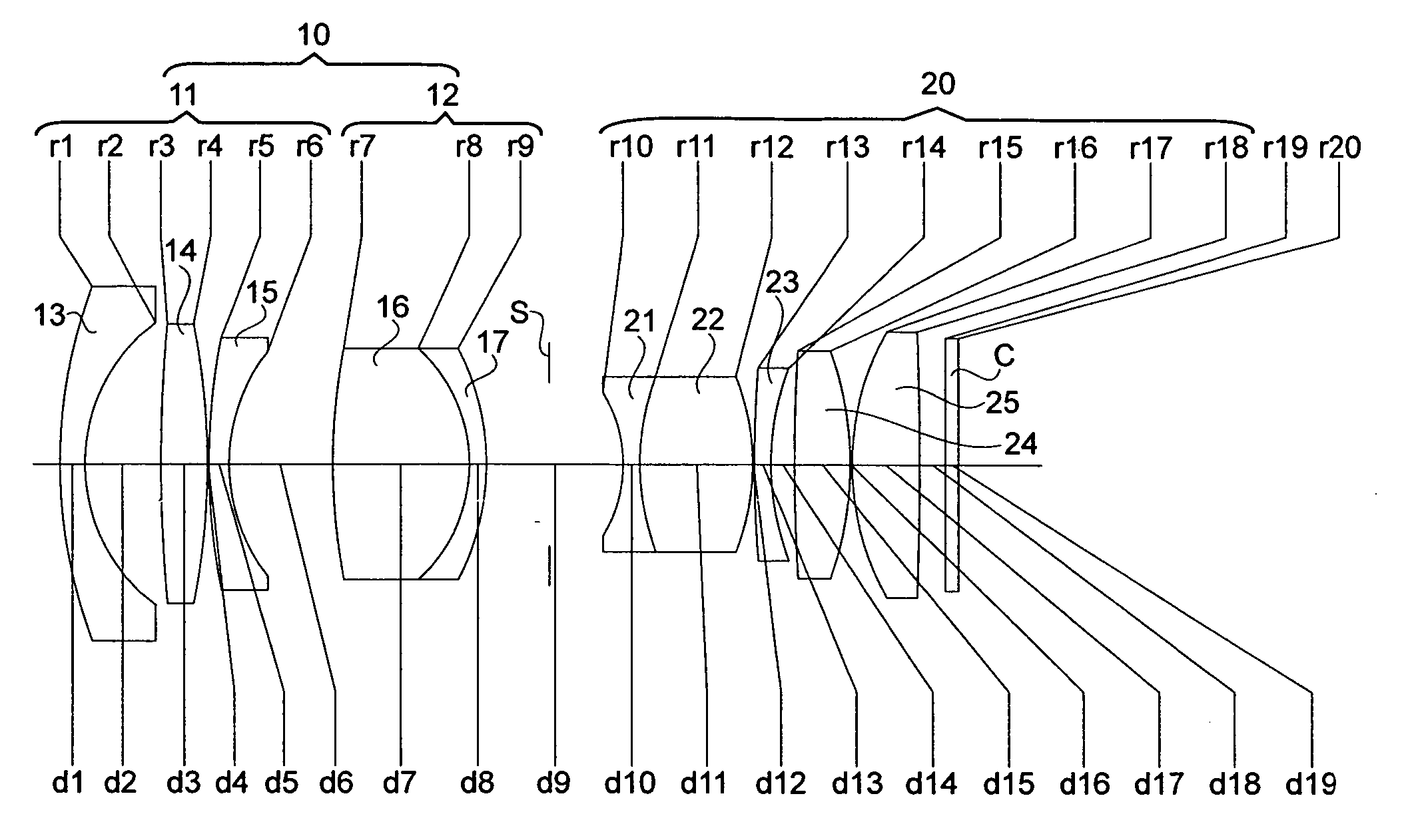
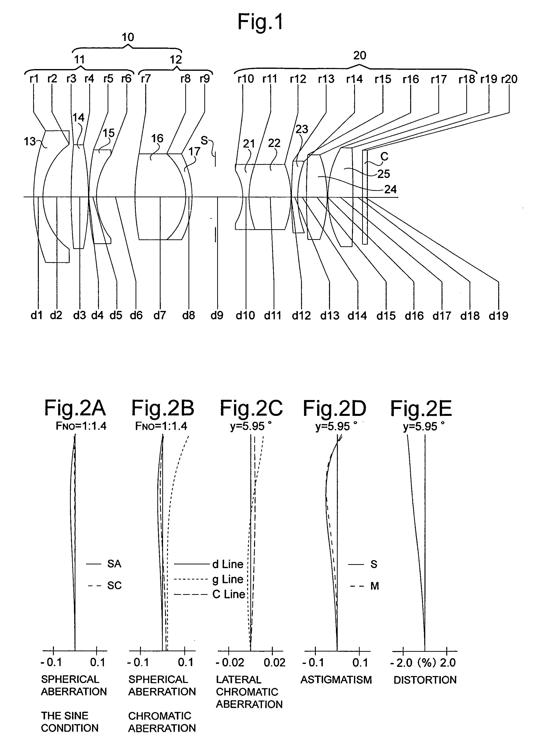
[0080]FIG. 1 is the lens arrangement of the wide-angle lens system according to the first embodiment of the present invention. FIGS. 2A through 2E show aberrations occurred in the lens arrangement shown in FIG. 1. Table 1 shows the numerical data of the first embodiment.

[0081] In the first embodiment, the positive second-sub-lens group 12 includes a positive lens element 16 and a negative lens element 17, which are cemented to each other, in this order from the object.

[0082] The diaphragm S is provided 3.72 behind surface No. 9 (the positive second-sub-lens group 12).

TABLE 1F = 1:1.4f = 8.24m = −0.031fB = 9.80OD = 250Surf. No.rdNdν129.9441.501.7725049.6210.4524.63——387.8372.781.8051825.44−42.6380.10——538.5441.201.7725049.6610.8066.17——737.2448.011.8044039.68−9.5981.001.8466623.89−15.3888.12——10−8.3021.001.6668033.01115.1136.821.7725049.612−13.9820.10——1372.3451.001.8466623.81416.2461.40——15113.1933.331.6180063.416−20.4980.10——1716.4774.001.7725049.618−218.8331.50——19∞0.751.51633...

embodiment 2

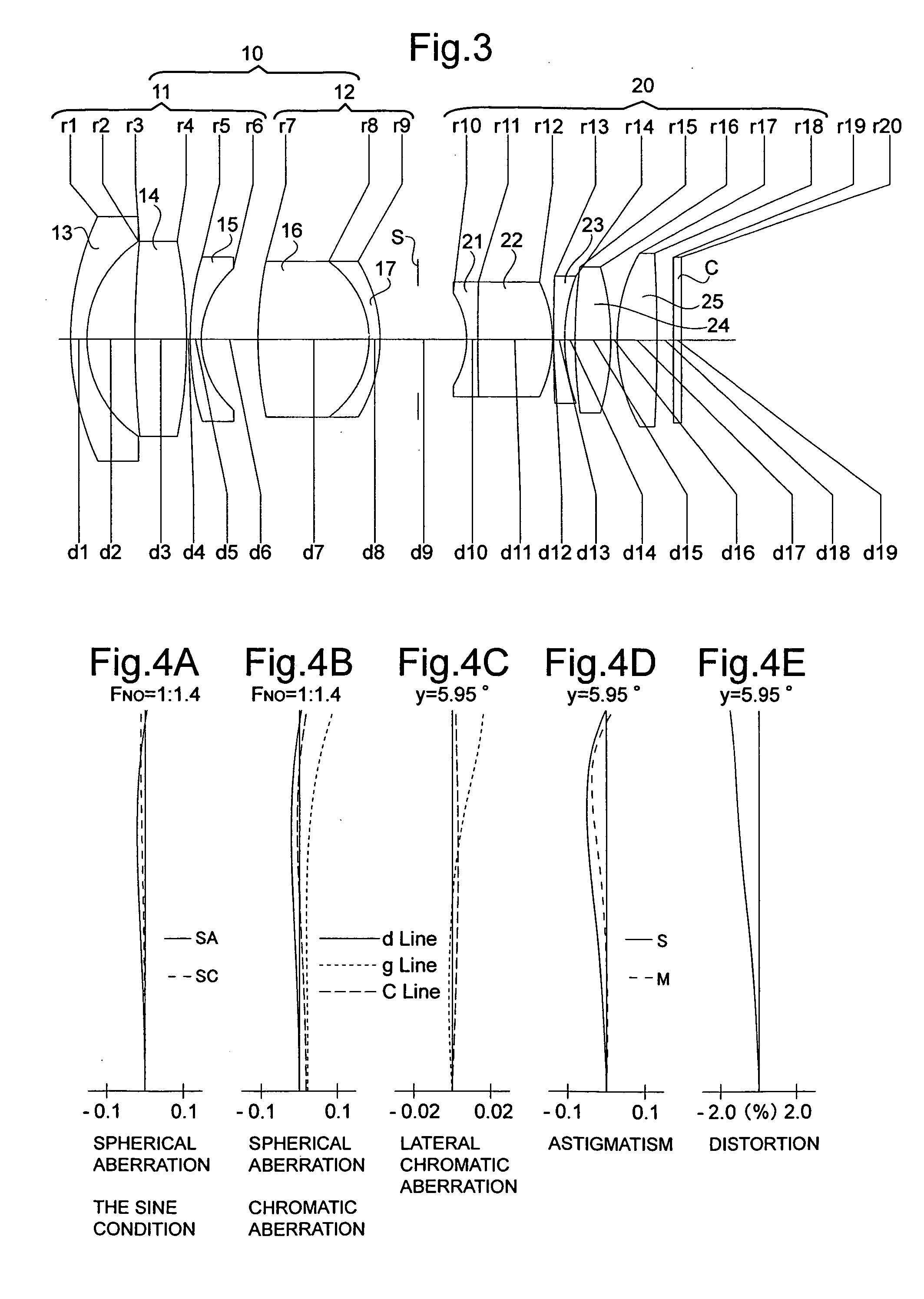
[0083]FIG. 3 is the lens arrangement of the wide-angle lens system according to the second embodiment of the present invention. FIGS. 4A through 4E show aberrations occurred in the lens arrangement shown in FIG. 3. Table 2 shows the numerical data of the second embodiment.

[0084] The basic lens arrangement of the second embodiment is the same as that of the first embodiment.

[0085] The diaphragm S is provided 3.43 behind surface No. 9 (the positive second-sub-lens group 12).

TABLE 2F = 1:1.4f = 8.24m = −0.031fB = 9.81OD = 250Surf. No.rdNdν126.3211.501.7725049.6210.8594.42——390.5644.721.8466623.84−48.8230.34——526.8871.001.8160046.668.7585.07——734.49210.241.8061040.98−8.7321.001.8466623.89−13.7737.88——10−8.0461.001.6727032.111204.4996.821.7725049.612−12.5330.10——13193.2741.001.8466623.81417.1630.96——1552.0083.261.6180063.416−23.8890.56——1716.5993.651.7725049.618−149.9381.50——19∞0.751.5163364.120∞———

embodiment 3

[0086]FIG. 5 is the lens arrangement of the wide-angle lens system according to the third embodiment of the present invention. FIGS. 6A through 6E show aberrations occurred in the lens arrangement shown in FIG. 5. Table 3 shows the numerical data of the third embodiment.

[0087] The basic lens arrangement of the third embodiment is the same as that of the first embodiment.

[0088] The diaphragm S is provided 3.36 behind surface No. 9 (the positive second-sub-lens group 12).

TABLE 3F = 1:1.4f = 8.24m = −0.031fB = 9.80OD = 250Surf. No.rdNdν131.5141.531.7725049.6210.9024.55——3102.2802.771.8051825.44−43.3500.10——533.5001.481.7725049.6610.9686.53——743.5808.011.8044039.68−10.0751.041.8466623.89−15.6588.25——10−8.3691.001.6668033.01114.0006.721.7725049.612−14.2480.11——1369.3201.001.8466623.81416.2561.44——15152.2403.341.6180063.416−19.8500.10——1716.3314.181.7725049.618−184.4091.50——19∞0.751.5163364.120∞———


PUM


Abstract

A wide-angle lens system includes a positive front lens group, a diaphragm, and a positive rear lens group. The front lens group includes a negative first-sub-lens group and a positive second-sub-lens group. The negative first-sub-lens group includes a negative lens element, a positive lens element, and a negative lens element. The front lens group satisfies the following conditions: 0.5<f / |f1a|<0.75 . . . (1) 0.5<|f1a| / f1b<1.0 . . . (2) 0.35<f / f1bi<0.6 . . . (3) wherein f: the focal length of the entire lens system; f1a: the focal length of the negative first-sub-lens group ; f1b:the focal length of the positive second-sub-lens group ; f1bi: the focal length of the most image-side surface of the positive second-sub-lens group; r1bi: the radius of curvature of the most image-side surface of the positive second-sub-lens group; and N1bi: a refractive index of the most image-side lens element of the positive second-sub-lens group.

Description

BACKGROUND OF THE INVENTION [0001] 1. Field of the Invention [0002] The present invention relates to a wide-angle lens system for examining an object at a finite distance with high definition, and for use in processing an object image. [0003] 2. Description of the Prior Art [0004] In the prior art, wide-angle lens systems for surveillance cameras have been disclosed in, e.g., Japanese Unexamined Patent Publication (hereinafter, JUPP) No. 2001-208967, JUPP No.H09-127413, JUPP No.H07-63986, and JUPP No.H04-11209. [0005] However, in the wide-angle lens system disclosed in each of these publications, distortion is noticeable, and such a wide-angle lens system cannot be used for image processing in which the optical ability with a higher definition is required. Furthermore, the overall length of the wide-angle lens system disclosed in these publications is relatively long compared to the focal length. [0006] On the other hand, there has been a wide-angle lens system which is designed for...

Claims


Application Information

Patent Timeline
Patent Type & Authority Applications(United States)
IPC IPC(8): G02B13/04
CPCG02B13/04
Inventor RYU, SACHIKOITO, TAKAYUKI
Owner RICOH IMAGING COMPANY
Learn More