Methods for repairing and for operating a memory component

a memory component and repair operation technology, applied in the field of memory components and repair operations, can solve the problems of reducing the linear dimension of memory components, in particular dram elements, and becoming increasingly difficult to develop cost-effective dram technologies, so as to maximize the refresh time of memory components, strengthen weak memory cells, and improve repair operations

Inactive Publication Date: 2006-06-15
POLARIS INNOVATIONS LTD
View PDF7 Cites 4 Cited by
  • Summary
  • Abstract
  • Description
  • Claims
  • Application Information

AI Technical Summary

Benefits of technology

[0021] One advantage of the present invention resides in the fact that it enables any desired compromise (which can be freely adapted to the respective application and its requirements) to be made between maximizing the refresh time of the memory component and the chip area required. The more redundant memory cells are provided, the better a repair operation is possible and the more weak memory cells can be strengthened by forming twins and the higher the predetermined limit value (beneath which a memory cell is deemed to be weak) of the data retention time can be set.
[0022] One particular advantage of the present invention resides in the fact that each operation of repairing a word line effectively makes it possible to only extend the data retention times of all of the memory cells which are assigned to the address of this word line. During conventional repair by replacement, simultaneously replacing all of the memory cells on a word line results in a good memory cell being replaced with a weak memory cell. The higher the number of weak memory cells or the higher said predetermined limit value is set, the more difficult it becomes to avoid this occurrence.
[0023] In the worst-case scenario, in accordance with the present invention, a good memory cell is selected and written to or read from together with a weak memory cell. Although this does not extend the effective data retention time, it does not shorten it either.
[0024] In this case, it is also no longer possible to distinguish between defective memory cells which, as a result of a short circuit, for example, have the data retention time 0 and weak memory cells which have a finite but excessively short data retention time. Defective memory cells are then no longer replaced in the conventional manner but rather all of the memory cells which are defective or weak are strengthened by forming twins.
[0025] In any event, the assignment of redundant and regular word lines is preferably optimized in order to achieve a maximum minimum data retention time within the memory component, which data retention time then represents the refresh time of the latter.
[0026] The present invention can be implemented most easily in connection with the conventional distinction between regular memory cells and word lines and redundant memory cells and word lines. However, it is also possible, at the cost of higher complexity of the operation of driving the word lines, to freely form pairs within an array, in which, as a result of the architecture, no distinction is made between a regular area and a redundant area.

Problems solved by technology

The reduction of the linear dimensions of memory components, in particular DRAM elements (DRAM=Dynamic Random Access Memory), is reaching physical and economic limits.
However, it is becoming increasingly more difficult to develop cost-effective DRAM technologies which require only 50 to 100 randomly distributed memory cells to be repaired per chip.
Memory cells which have a short circuit or whose data retention time falls below a first predetermined limit value and is thus unacceptably short are defective.
The higher the proportion of weak cells in the total number of memory cells of a DRAM element or else of an individual memory block on a DRAM element, the more complicated the repair operation becomes.
The risk or likelihood, when repairing or replacing a defective or weak memory cell on a regular word line, of good memory cells on the regular word line that is to be replaced simultaneously being replaced with weak memory cells on the redundant word line consequently increases.
The result is that the number of redundant word lines required and thus the chip area required and the production costs increase more than proportionally.
Although there is a high storage capacity in the individual-cell operating mode, it has the disadvantages described above.

Method used


Image

  • Methods for repairing and for operating a memory component
  • Methods for repairing and for operating a memory component
  • Methods for repairing and for operating a memory component

Examples


Embodiment Construction

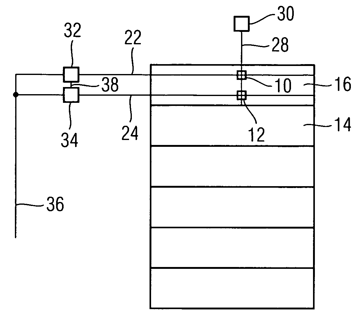
[0036]FIG. 1 is a diagrammatic illustration of a memory component in accordance with the present invention. The memory component has a plurality of memory cells 10, 12 which are arranged in an array 14. To make the illustration clear, only two memory cells 10, 12 are illustrated although the array 14 may comprise overall a virtually arbitrary number of memory cells. The array 14 is subdivided into a plurality of blocks 16. Each block 16 comprises a plurality of word lines 22, 24 which are preferably essentially arranged parallel to one another or with few crossovers between one another. For clarity, only 2 of a total of, for example, a few 100 word lines are in turn illustrated in the first block 16.

[0037] A plurality of bit lines 28 intersect the word lines 22, 24, only one bit line 28 being illustrated in turn. Each memory cell 10, 12 is arranged at the crossover between a word line 22, 24 and a bit line 28. Activating a word line 22, 24 or applying an appropriate potential to th...


PUM


Abstract

In a method for repairing a memory component, data retention times of regular memory cells are determined. Weak regular memory cells having a data retention time that is shorter than a predetermined limit value are determined. A device is programmed in such a manner that a write or read access to the weak regular memory cell is simultaneously also effected for a redundant memory cell in order to jointly read from, or write to, the weak regular memory cell and the redundant memory cell.

Description

CROSS-REFERENCE TO RELATED APPLICATIONS [0001] This application claims foreign priority benefits under 35 U.S.C. §119 to co-pending German patent application number DE 10 2004 054 968.0, filed Nov. 13 2004. This related patent application is herein incorporated by reference in its entirety. BACKGROUND OF THE INVENTION [0002] 1. Field of the Invention [0003] The present invention relates to methods for repairing and operating a memory component and to a memory component, which methods and memory component make it possible to extend refresh times. [0004] 2. Description of the Related Art [0005] The reduction of the linear dimensions of memory components, in particular DRAM elements (DRAM=Dynamic Random Access Memory), is reaching physical and economic limits. The ever more extensive reduction of the dimensions of the memory cells and their features requires a very high technical outlay that is continuing to rise. One example is the introduction of dielectrics having a very high dielec...

Claims


Application Information

Patent Timeline
Patent Type & Authority Applications(United States)
IPC IPC(8): G11C29/00G11C7/00
CPCG11C11/401G11C29/785G11C29/816
Inventor POECHMUELLER, PETER
Owner POLARIS INNOVATIONS LTD
Why Eureka
Try Eureka