Fuel cell stack with multiple groups of cells and flow passes

a fuel cell and flow pass technology, applied in the direction of fuel cells, heat exhanger conduits, lighting and heating apparatus, etc., can solve the problems of increasing the cost of the stack, so as to improve the capability and performance of water removal, improve the uniformity of reactant gas distribution, and improve the effect of water removal ability

Inactive Publication Date: 2006-06-15
HYTEON
View PDF73 Cites 13 Cited by
  • Summary
  • Abstract
  • Description
  • Claims
  • Application Information

AI Technical Summary

Benefits of technology

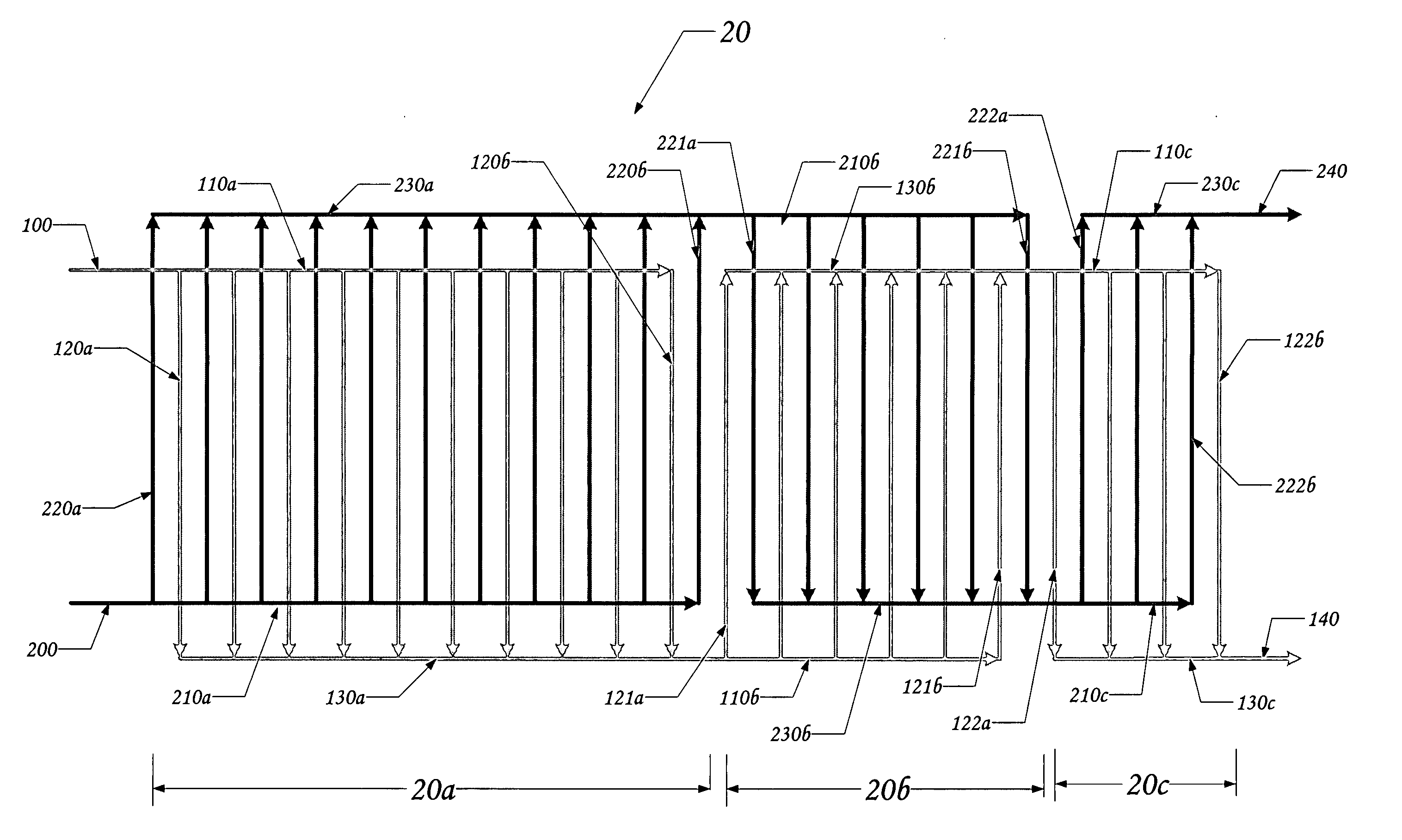
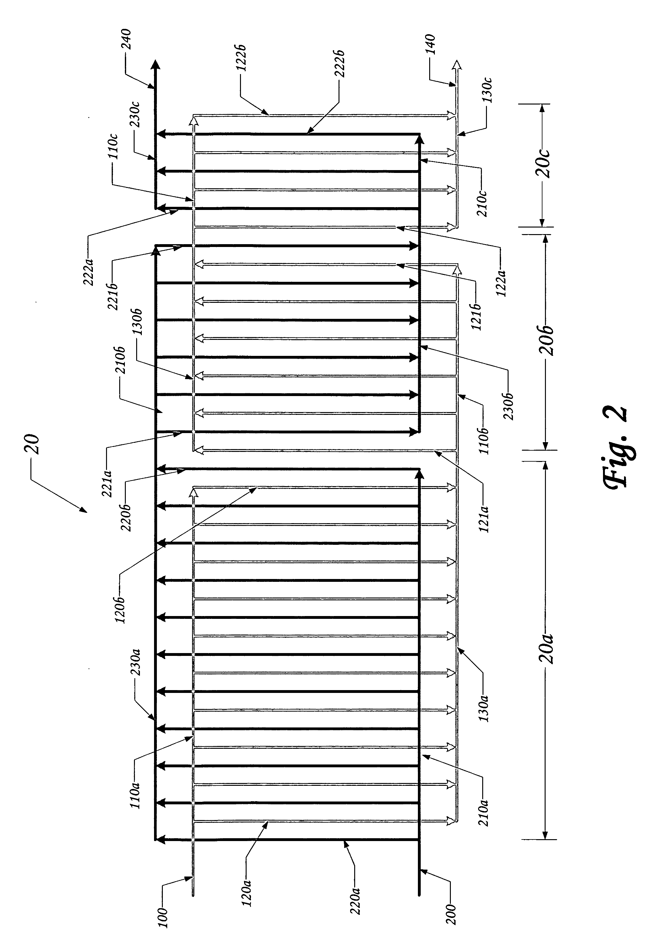
[0014] The present invention improves the uniformity of reactant gas distribution into individual cells. This can be achieved by using conventional fuel cell stack designs and manufacturing, and therefore without significant cost addition.
[0015] The present invention also provides a fuel cell stack that improves the capability and performance of water removal. This is achieved without increasing the reactant gas, especially cathode air, stoichiometry.
[0016] The present invention provides a fuel cell stack that improves the fuel cell performance. The performance improvement can be achieved with local, but not overall, increased reactant gas stoichiometry, which improves both mass transfer and water removal.
[0017] The present invention also provides a fuel cell stack that allows using lower reactant stoichiometry, especially cathode air, but without lowering this parameter for any single cell. The operation of lower overall stoichiometry will reduce the parasitic power consumption associated with the reactant gas (particularly cathode air) compression and delivery, and thus increase the fuel cell system efficiency. The increased in-cell stoichiometry, under circumstances of lower overall stoichiometry, will increase the cell performance due to improvement in mass transfer and water removal.

Problems solved by technology

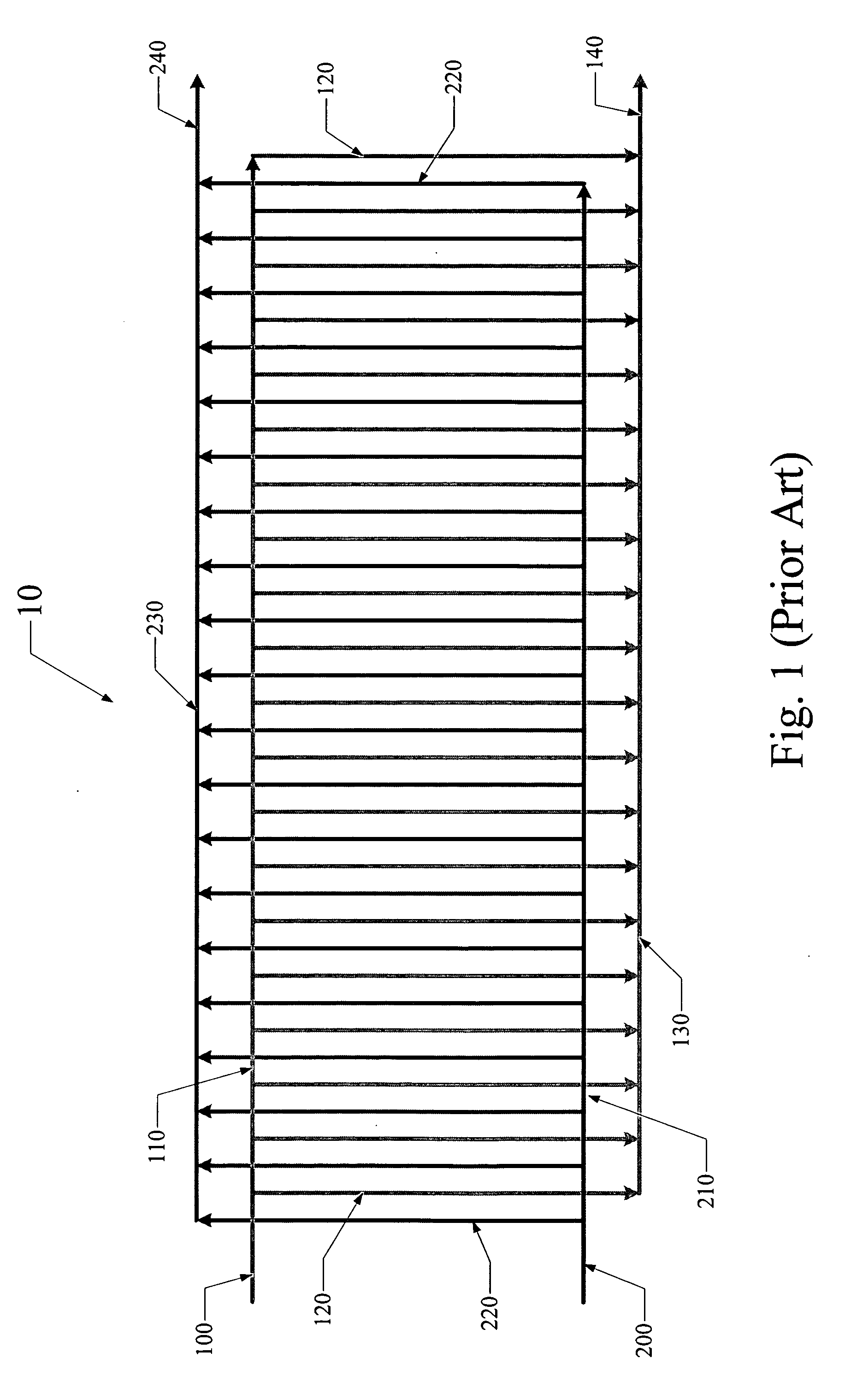
Firstly, it has been well documented in the field that the performance of a fuel cell stack having a plurality of cells is generally lower than the performance of a single cell.
The decline in the performance, which is more severe for the cells located at either ends or at both ends of the stack, is believed to be due, at least in part, to the fact that reactant distribution into individual cells of a stack becomes non-uniform.
Operation of a fuel cell stack with high air stoichiometry, on the other hand, has been one of the biggest parasitic power consumptions due to cathode air compression and delivery.

Method used


Image

  • Fuel cell stack with multiple groups of cells and flow passes
  • Fuel cell stack with multiple groups of cells and flow passes
  • Fuel cell stack with multiple groups of cells and flow passes

Examples


example 1

[0048] In this example, O2 utilization is increased from 33% to 67%.

Total number of cells: 100

Overall stoichiometry of reactant O2: 1.5

[0049] Design local stoichiometry of reactant O2: 3.0

TABLE 3Local stoichiometry of reactantO2 after cell number adjustmentCell Group 1503Cell Group 2303.3Cell Group 3203.5

example 2

[0050] In this example, O2 utilization is increased from 25% to 67%.

Total number of cells: 100

Overall stoichiometry of reactant O2: 1.5

[0051] Design local stoichiometry of reactant O2: 4.0

TABLE 4Local stoichiometry of reactantO2 after cell number adjustmentCell Group 1383.9Cell Group 2284.0Cell Group 3204.2Cell Group 4144.6

example 3

[0052] In this example, 02 utilization is increased from 25% to 80%.

Total number of cells: 100

Overall stoichiometry of reactant O2: 1.25

[0053] Design local stoichiometry of reactant O2: 4.0

TABLE 5Local stoichiometry of reactantO2 after cell number adjustmentCell Group 1314.0Cell Group 2243.9Cell Group 3183.9Cell Group 4143.7


PUM

PropertyMeasurementUnit
temperatureaaaaaaaaaa
physical stateaaaaaaaaaa
resistanceaaaaaaaaaa

Abstract

There is described a method of flowing reactants through a fuel cell stack having a plurality of fuel cells, the method comprising: dividing the stack into a plurality of groups, each of the groups connected together electrically in series; selecting a number of the groups and a number of cells in each of the groups to maintain a substantially constant stoichiometry for each of the groups, wherein a number of the fuel cells in each of said groups is decreasing from upstream to downstream; and distributing the reactants in series to each of the groups and in parallel within each of the groups.

Description

CROSS-REFERENCE TO RELATED APPLICATIONS [0001] This application is the first filed application for the present invention. TECHNICAL FIELD [0002] The present invention relates to devices which produce an electrical current by means of a chemical reaction or change in physical state, and more specifically, sub-combinations of the device and the process of operating the same. BACKGROUND OF THE INVENTION [0003] A fuel cell is an electrochemical device that converts fuel and oxidant directly into electricity and a reaction by-product of water through an electrolytic reaction that strips hydrogen molecules of their electrons and protons. Ultimately, the stripped electrons are collected into some form of usable electric current, by resistance or by some other suitable means. The protons react with oxygen to form water as a reaction by-product. [0004] Typically, a single Proton Exchange Membrane (PEM) fuel cell, operating at a temperature of around 70-80° C., consists of a combined solid po...

Claims


Application Information

Patent Timeline
Patent Type & Authority Applications(United States)
IPC IPC(8): H01M8/00H01M8/04
CPCF28F2210/10H01M8/04089H01M8/249Y02E60/50
Inventor BAI, DINGRONGCHOUINARD, JEAN-GUYELKAIM, DAVID
Owner HYTEON
Why Eureka
Try Eureka