Method for manufacturing a non-fogging element and device for activating such an element

Inactive Publication Date: 2006-06-15
FLABEG GMBH & CO KG
View PDF13 Cites 17 Cited by
  • Summary
  • Abstract
  • Description
  • Claims
  • Application Information

AI Technical Summary

Benefits of technology

[0015] In this case, the or each gas burner may be positioned relative to the conveying device in such a manner that the visible flame tip of the gas flame is is located slightly, for example about 10 mm to 20 mm, above the surface of a passing substrate. This enables reliable, stable and reproducible treatment results to be obtained by the oxidizing properties of the gas flame, the presence of free radicals, and the water vapor released during combustion.
[0016] The device can be designed for sequential treatment of a plurality of separate elements by suitable selection of the conveying device. In particular, provision can also be made to treat convex or curved elements having a relatively large surface area. These elements can, in particular, be so-called “spherical caps” from whi

Problems solved by technology

However, the hydrophilicity gradually disappears over time, which is especially attributed to contaminations attaching to the hydroxyl groups of the coating surface.
However, during the manufacture of such a non-fogging element, the activation step for the first activation of the photocat

Method used


Image

  • Method for manufacturing a non-fogging element and device for activating such an element
  • Method for manufacturing a non-fogging element and device for activating such an element

Examples


Example

[0021] In the Figures, like reference numerals denote like parts.

DETAILED DESCRIPTION

[0022] The reactive treatment of the surface could be accomplished, for example, by the action of a sufficiently high temperature, in particular under atmospheric conditions, for example, in an oven. Alternatively or additionally, concepts such as plasma treatment in vacuum or plasma treatment in air could, in principle, be used, given the appropriate selection of the process parameters. In one advantageous embodiment, however, a corona treatment is proposed for the reactive treatment of the surface layer during the activation step; the surface being treated with a corona discharge when carrying out the activation step. However, relatively short treatment times and a relatively low level of equipment complexity for carrying out the activation step can be achieved in an advantageous embodiment by reactively treating the surface layer with a gas flame.

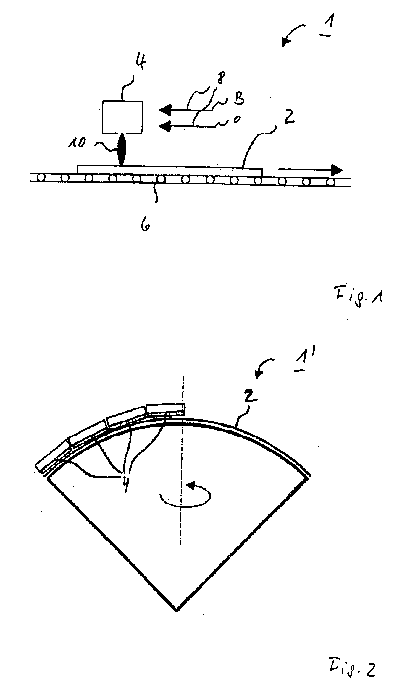
[0023] In order to activate the surface coating...


PUM

PropertyMeasurementUnit
Lengthaaaaaaaaaa
Lengthaaaaaaaaaa
Speedaaaaaaaaaa

Abstract

A method for manufacturing an element includes providing a surface layer including a photocatalytic material, and subjecting the surface layer to an activation process including reactively treating the surface layer.

Description

[0001] Priority is claimed to provisional application No. 60 / 634,475, filed Dec. 9, 2004, the entire subject matter of which is hereby incorporated by reference herein.[0002] The present invention relates to a method for manufacturing an element, in which a surface layer of a photocatalytic material is subjected to an activation step. The present invention further relates to a device for activating a surface layer of a photocatalytic material of such an element. BACKGROUND [0003] In many applications of glasses, such as rearview mirrors or windshields of motor vehicles, window panes of buildings, traffic mirrors, lenses, or glass covers for instruments, it is desirable to keep the respective glass free of condensation even at comparatively low ambient temperatures and high ambient humidity. For glasses, this can be achieved by manufacturing a non-fogging element by providing the surface with an anti-fogging coating usually having so-called “hydrophilic” or “super-hydrophilic” proper...

Claims


Application Information

Patent Timeline
IPC IPC(8): B01J23/00
CPCB01J21/063B01J35/004B01J37/0238B01J37/349B60R1/0602C03B29/08C03C17/23C03C17/245C03C17/2456C03C23/006C03C2217/71C03C2217/75C03C2218/152C03C2218/32
Inventor VOGL, STEFAN
Owner FLABEG GMBH & CO KG
Why Eureka
Try Eureka