This helps you quickly interpret patents by identifying the three key elements:
Problems solved by technology
Method used
Benefits of technology
Benefits of technology
[0021] Preferably, the lancing apparatus according to the present invention may comprise a controller that controls a depth or speed of insertion of the inserting elemen
Problems solved by technology
Such pressure against the skin Sk / Sk1 may lead to insufficient bleeding from the sticking point.
In such a case the lancet 91 is inserted too deeply into the skin Sk, which not only causes a considerable damage on the skin Sk, but also makes the patient feel an intolerable pain.
Method used
Image
Click on the blue label to locate the original text in one second.
Reading with bidirectional positioning of images and text.
Examples
first embodiment
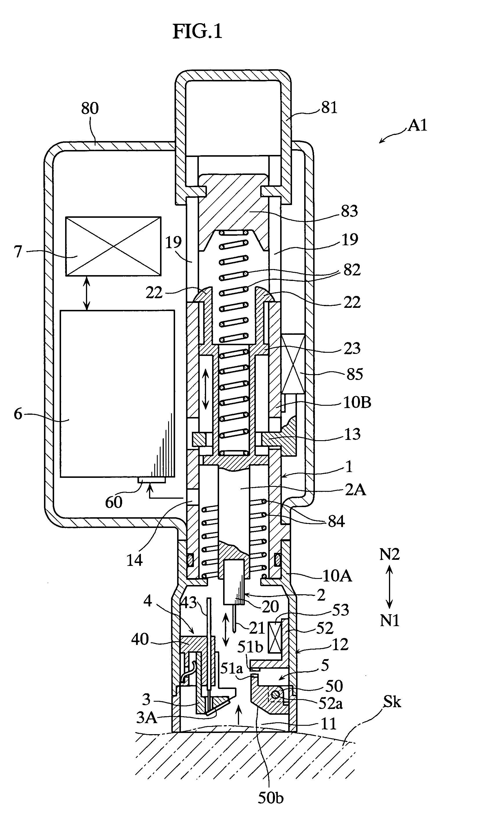
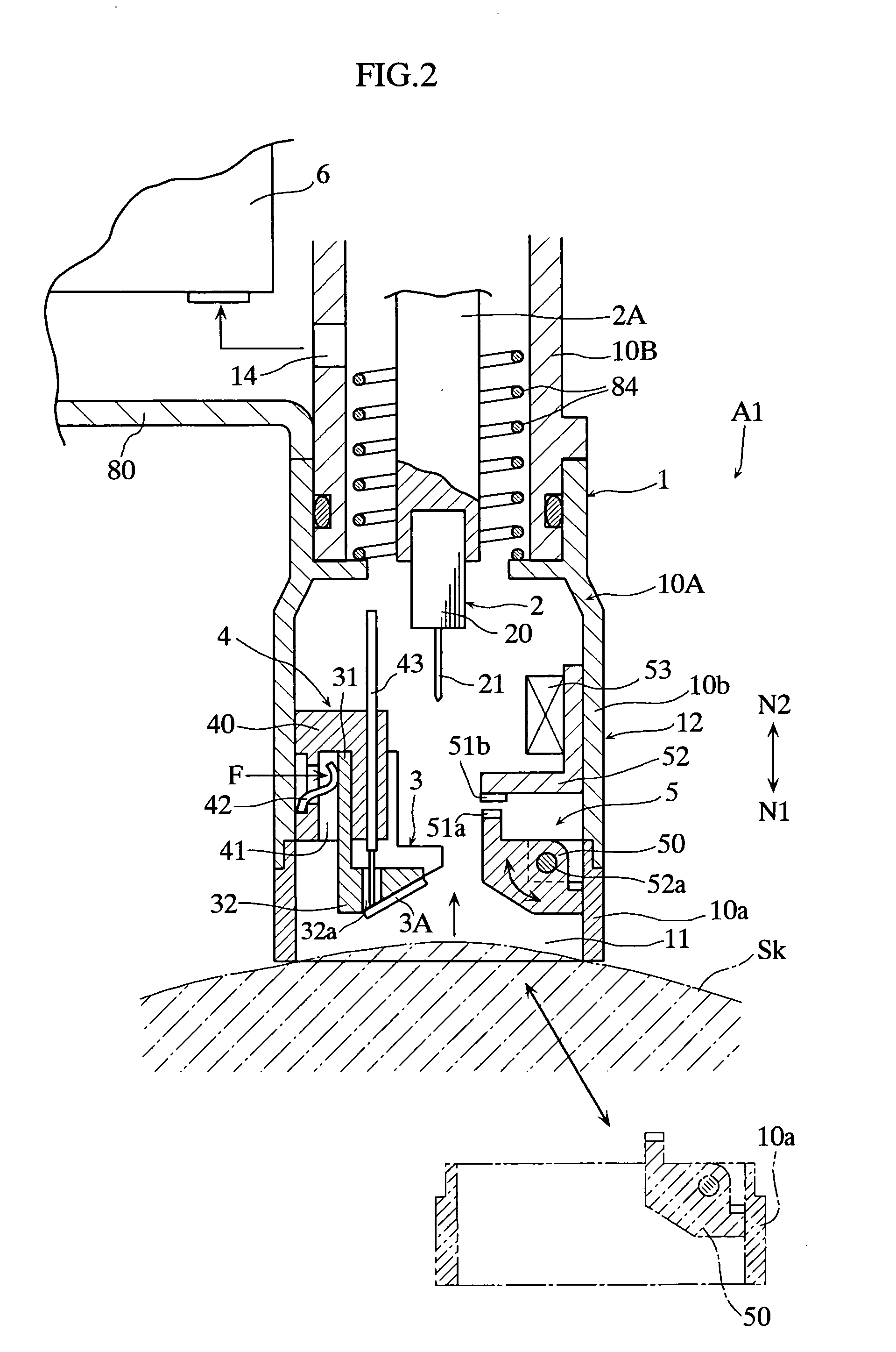
[0040]FIGS. 1 and 2 illustrate a lancing apparatus according to the present invention. As explicitly shown in FIG. 1, the lancing apparatus A1 includes a housing 1, a lancet holder 2A that holds a lancet 2, an attachment base 4 to which a sensor holder 3 is attached, a detection switch 5, a pressure sensor 53, a pump 6, a control unit 7, and other components to be subsequently described.
[0041] The housing 1 is a combination of two sleeves 10A, 10B of a generally circular cylindrical shape, and a central portion and an upper portion in a direction of N1-N2 in FIG. 1 are enclosed in an outer case 80. In a portion close to the forward end of the housing 1 a cylindrical portion 12 with an opening 11 is provided, the forward end portion of which is brought into contact with a human skin Sk when using the lancing apparatus A1.
[0042] The sleeve 10A includes a first portion 10a and a second portion 10b. The first portion 10a supports a movable body 50 of the detection switch 5 to be descri...
second embodiment
[0079]FIG. 9 depicts a lancing apparatus according to a In the lancing apparatus A2 shown therein, the detection switch 5 is provided with a load sensor 54. The load sensor 54 is attached to the bracket 52, and detects a load F1 applied thereto when pressed by the movable body 50 because of the swelling motion of the skin Sk. The load sensor 54 may be attached to the movable body 50 instead.
[0080] Load data detected by the load senor 54 is input to the control unit 7 (not shown in FIG. 9, but in FIG. 1). The control unit 7 in the lancing apparatus A2 performs the following control to maintain the swelling height of the skin Sk at a generally constant level.
[0081] Referring to the flowchart according to FIG. 10, when the control unit 7 decides that the load sensor 54 has been turned on pressed by the movable body 50 (YES at S10), the control unit 7 defines a load range (between an upper limit Fu and a lower limit Fb shown in FIG. 11) that serves as a target of the control (S11). At...
third embodiment
[0088]FIG. 12 illustrates a lancing apparatus according to a In the lancing apparatus A3, the detection switch 5 is located right above the attachment base 4, while the sensor holder 3 is vertically movable. Accordingly, in the lancing apparatus A3, the swelling motion of the skin Sk causes the sensor holder 3 to ascend thus to press the load sensor 54.
[0089] In the lancing apparatus A3, since the sensor holder 3 also serves to detect the swelling height of the skin Sk, the number of parts of the device can be reduced, which leads to reduction in manufacturing cost and in dimensions of the device.
PUM
Abstract
This invention relates to a lancing apparatus (A1) used for inserting an insertion element (21) into a human skin (Sk) for sampling a body fluid. The lancing apparatus (A1) includes a housing (1) with a cylindrical portion (12) brought into contact with the skin (Sk), a negative pressure generator (6) that generates a negative pressure inside the cylindrical portion (12) to cause the skin (Sk) to swell upward, and a detector (5) that detects that the skin (Sk) has been raised to a predetermined height inside the cylindrical portion (12).
Description
TECHNICAL FIELD [0001] The present invention relates to a lancing apparatus for use in inserting a needle into the human skin for sampling a body fluid such as blood, or a tissue. BACKGROUND ART [0002] When treating diabetes patients, it is a common practice to measure the glucose concentration in blood sampled from the patient, for developing a treatment plan according to the measured value. Devices currently employed for such a purpose include a lancing apparatus according to JP-A 2001-346781, which is shown in FIG. 18A. [0003] The lancing apparatus 9 shown therein includes a lancet 91 advanceably disposed in a cylindrical portion 90 of a housing with an opening at its outer end portion. The cylindrical portion 90 includes a flange portion 93 with a small hole 92 located at a central portion, and a glucose concentration meter 94 is disposed so as to project halfway into the hole 92. The lancing apparatus 9 also includes an electric pump (not shown) which, when activated, generates...
Claims
Application Information
Patent Timeline
Application Date:The date an application was filed.
Publication Date:The date a patent or application was officially published.
First Publication Date:The earliest publication date of a patent with the same application number.
Issue Date:Publication date of the patent grant document.
PCT Entry Date:The Entry date of PCT National Phase.
Estimated Expiry Date:The statutory expiry date of a patent right according to the Patent Law, and it is the longest term of protection that the patent right can achieve without the termination of the patent right due to other reasons(Term extension factor has been taken into account ).
Invalid Date:Actual expiry date is based on effective date or publication date of legal transaction data of invalid patent.

