Autonomous mobile robot

a mobile robot and autonomous technology, applied in the direction of process and machine control, distance measurement, instruments, etc., can solve the problem of difficulty in having an inner space for such a robo

Active Publication Date: 2006-06-15
HONDA MOTOR CO LTD
View PDF8 Cites 43 Cited by
  • Summary
  • Abstract
  • Description
  • Claims
  • Application Information

AI Technical Summary

Problems solved by technology

Therefore, it is difficult for such a robot to have an inner space enough to accommodate both a road surface sensing device and a current location verification device.

Method used


Image

  • Autonomous mobile robot
  • Autonomous mobile robot
  • Autonomous mobile robot

Examples


Embodiment Construction

[0035] A detailed description will be given below, of an autonomous mobile robot according to an embodiment of the present invention, with reference to accompanying drawings. In the following description, the same reference numerals are given to the same parts, and duplicate description is therefore omitted.

[0036] First, an autonomous mobile robot of one embodiment of the present invention will be given below, with reference to FIG. 1. Thereinafter, an autonomous mobile robot is just called “robot”, occasionally.

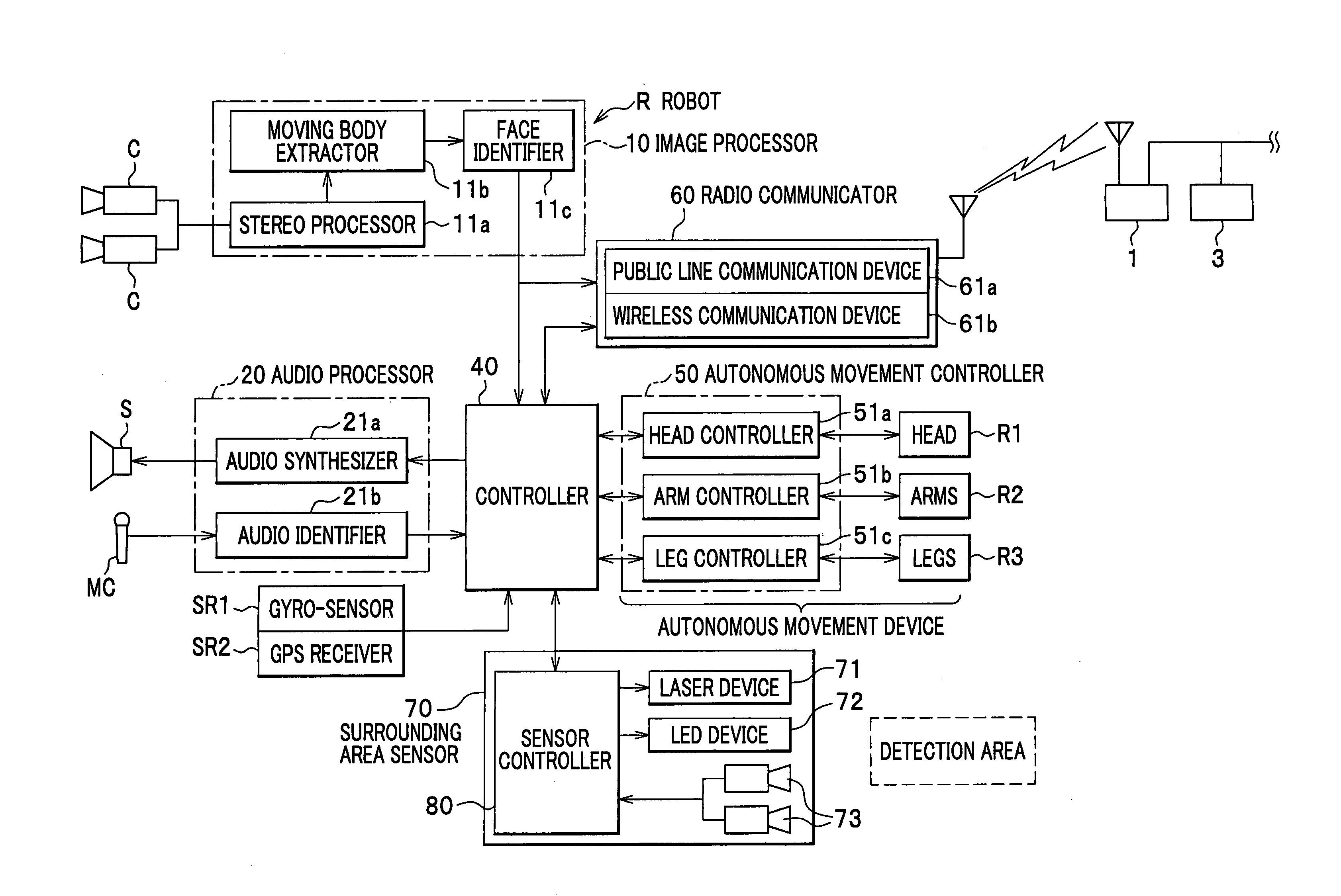
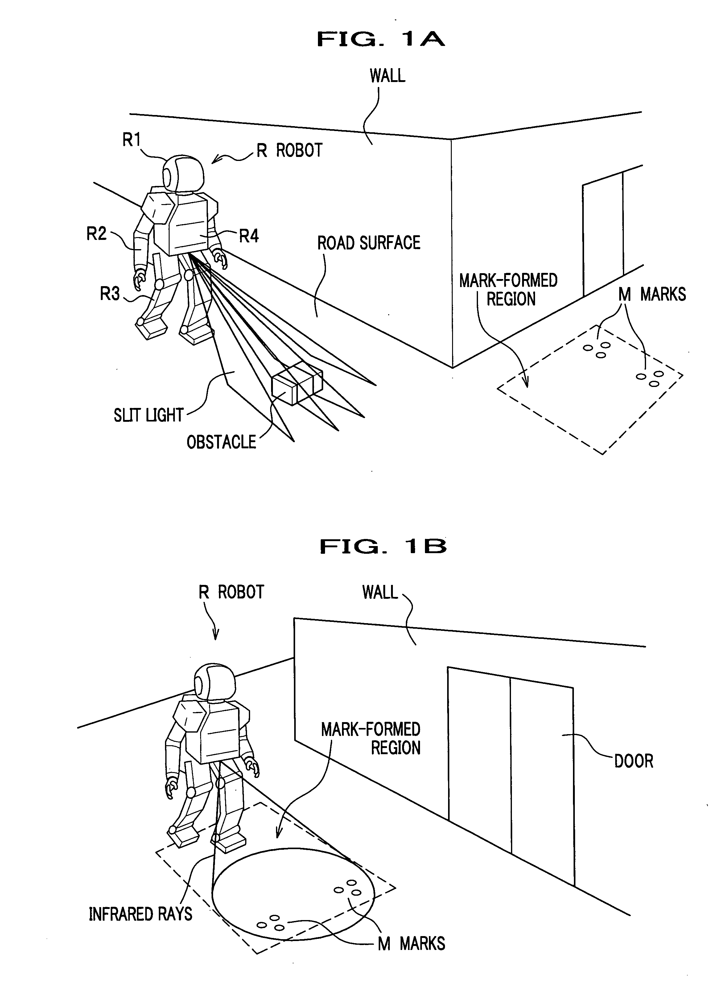
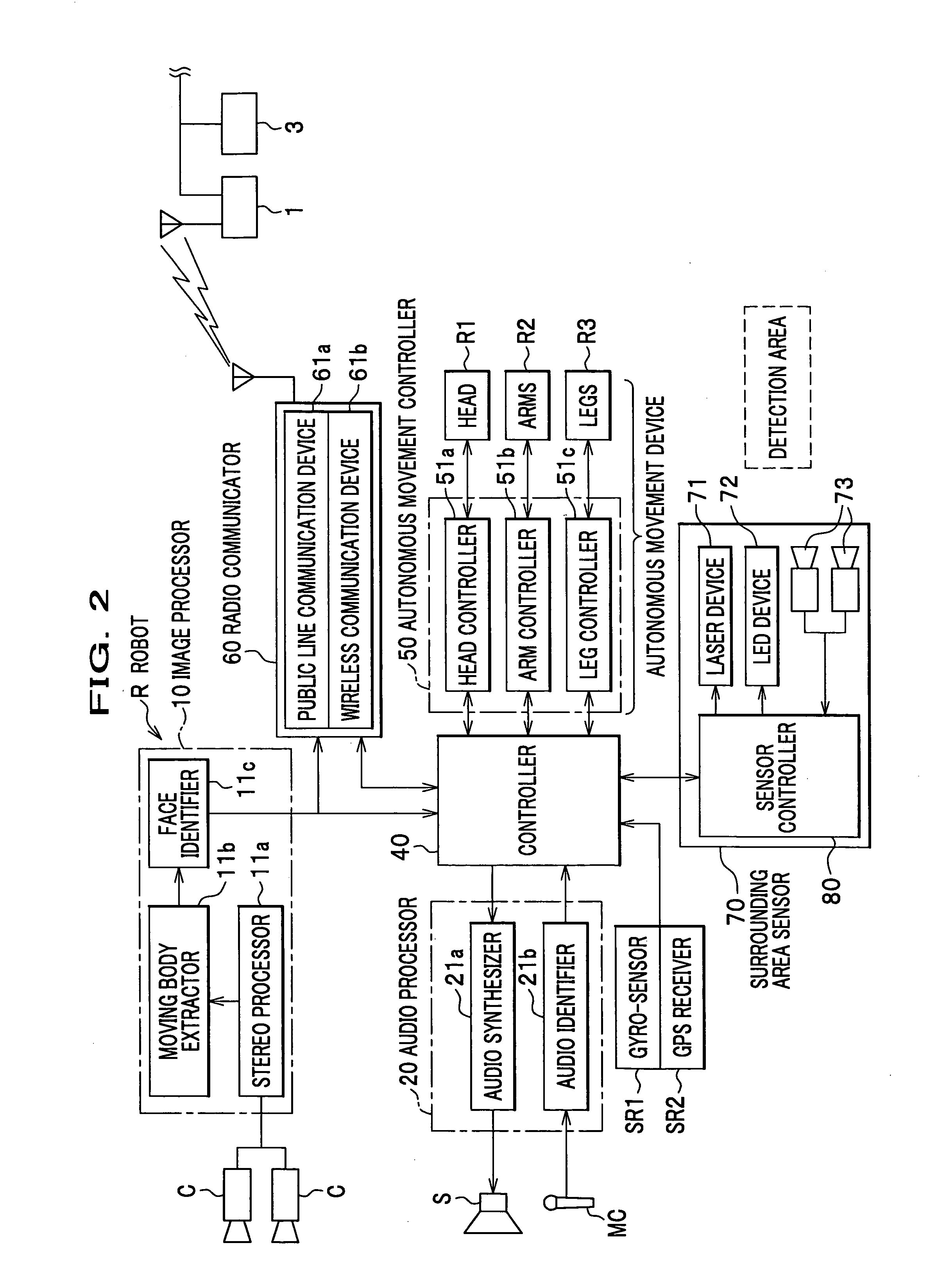
[0037] Referring to FIGS. 1A and 1B, a robot R includes a head R1, arms R2, legs R3 and a body R4. The head R1, arms R2 and legs R3 are driven by individual actuators, and the bipedal movement is controlled by an autonomous movement controller 50 (see FIG. 2). Herein, the legs R3 which are called “legged moving mechanism”. The detail of the bipedal movement is disclosed by Japanese Unexamined Patent Application Publication 2001-62760, etc.

[0038] The robot R moves around w...


PUM


Abstract

Disclosed is a space-saving autonomous mobile robot capable of switching two types of light irradiation appropriately. The robot includes a moving mechanism, an autonomous movement controller for controlling the moving mechanism, a self-location recognition unit for sensing a self-location of the robot, a map data storage unit for storing a map data on locations of marks, a slit light device for irradiating a detection area with slit light, an infrared device for irradiating a detection area with infrared rays, and a switch determination unit for comparing a mark-formed region and the self-location, and then, for switching between the slit light and infrared devices, based on the comparison result. Moreover, the infrared device irradiates the detection area when the self-location is within the mark-formed region, while the slit light device irradiates the detection area when the self-location is outside the mark-formed region.

Description

CROSS-REFERENCE TO RELATED APPLICATIONS [0001] This application claims the benefit of Japanese Patent Application 2004-361905 filed on Dec., 14, 2004, the disclosure of which is incorporated herein by reference. BACKGROUND OF THE INVENTION [0002] 1. Field of the Invention [0003] The present invention relates to autonomous mobile robots, generally. More specifically, the present invention is directed to an autonomous mobile robot equipped with both a road surface sensing device and a current location verification device. [0004] 2. Description of the Related Art [0005] A typical mobile robot is equipped with a device for checking a road surface, which is called “road surface sensing device” This device has a function of determining whether or not there is any obstacle in front of the robot. Specifically, the device irradiates a road surface in front of the robot with predetermined slit light, and then, captures an image of the irradiated area. Finally, it analyzes the pattern of the l...

Claims


Application Information

Patent Timeline
Patent Type & Authority Applications(United States)
IPC IPC(8): G06F19/00B25J5/00B25J13/08G05D1/02
CPCG05D1/0234G05D1/024G05D1/0242G05D1/0251G05D1/027G05D1/0274G05D1/0278G05D2201/0217
Inventor WATABE, TOMOKISUGINO, TSUKASAKAWABE, KOJIASATANI, MINAMIOSADA, TAKUYOSHIIKE, TAKAHIDENAKAYAMA, TAKASHIFUJITA, SHINTAROU
Owner HONDA MOTOR CO LTD
Why Eureka
Try Eureka