Air purifier

a technology of air purifier and air filter, which is applied in the field of air purifier, can solve the problem of not producing enough purified air for indoor use, and achieve the effect of thoroughly eliminating odors

Inactive Publication Date: 2006-06-22
HUANG SHAO SHIH
View PDF7 Cites 8 Cited by
  • Summary
  • Abstract
  • Description
  • Claims
  • Application Information

AI Technical Summary

Benefits of technology

[0004] It is another objective of the present invention to

Problems solved by technology

The window type expels exhaust to the outdoor, but it can't pr

Method used


Image

  • Air purifier
  • Air purifier
  • Air purifier

Examples


Embodiment Construction

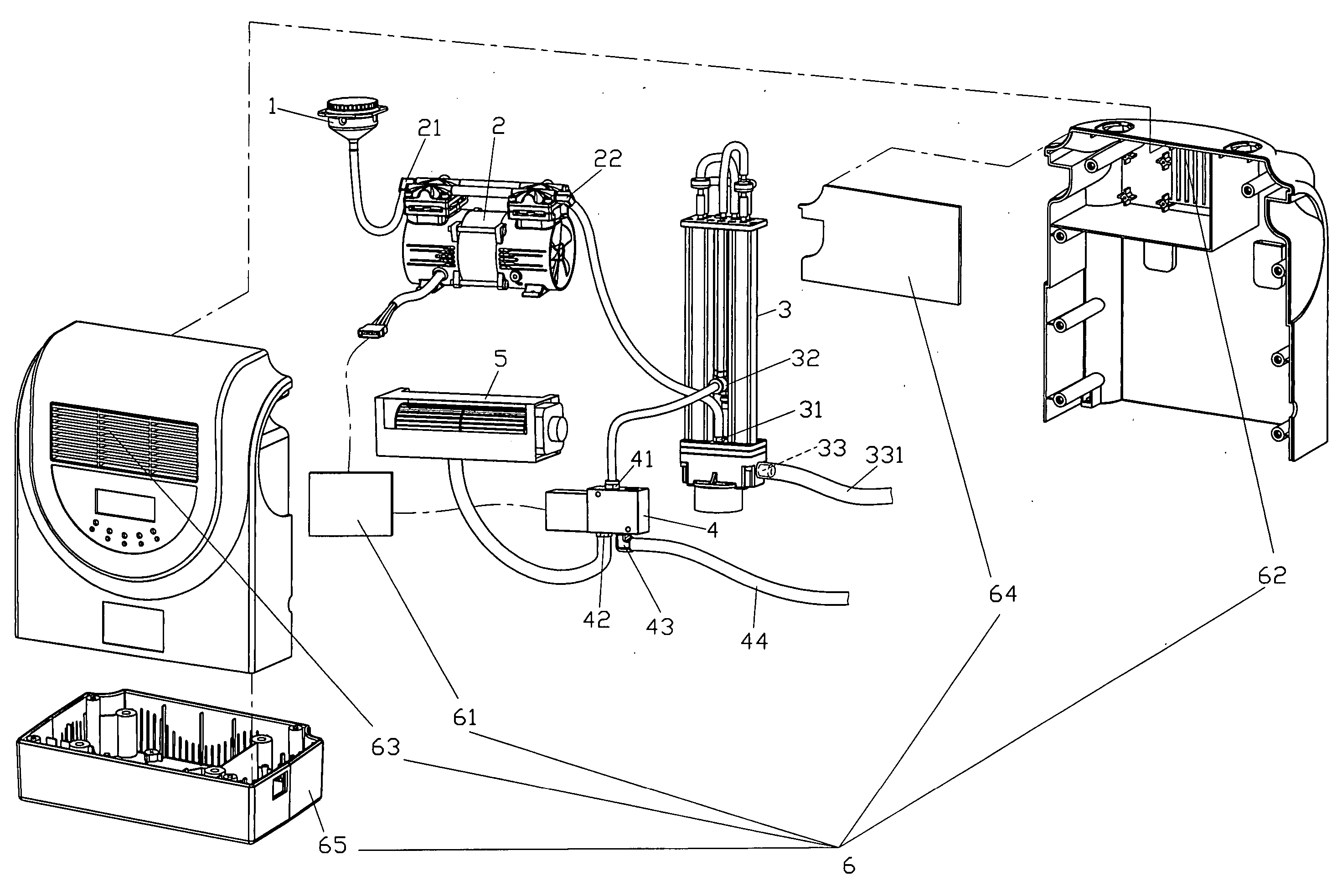
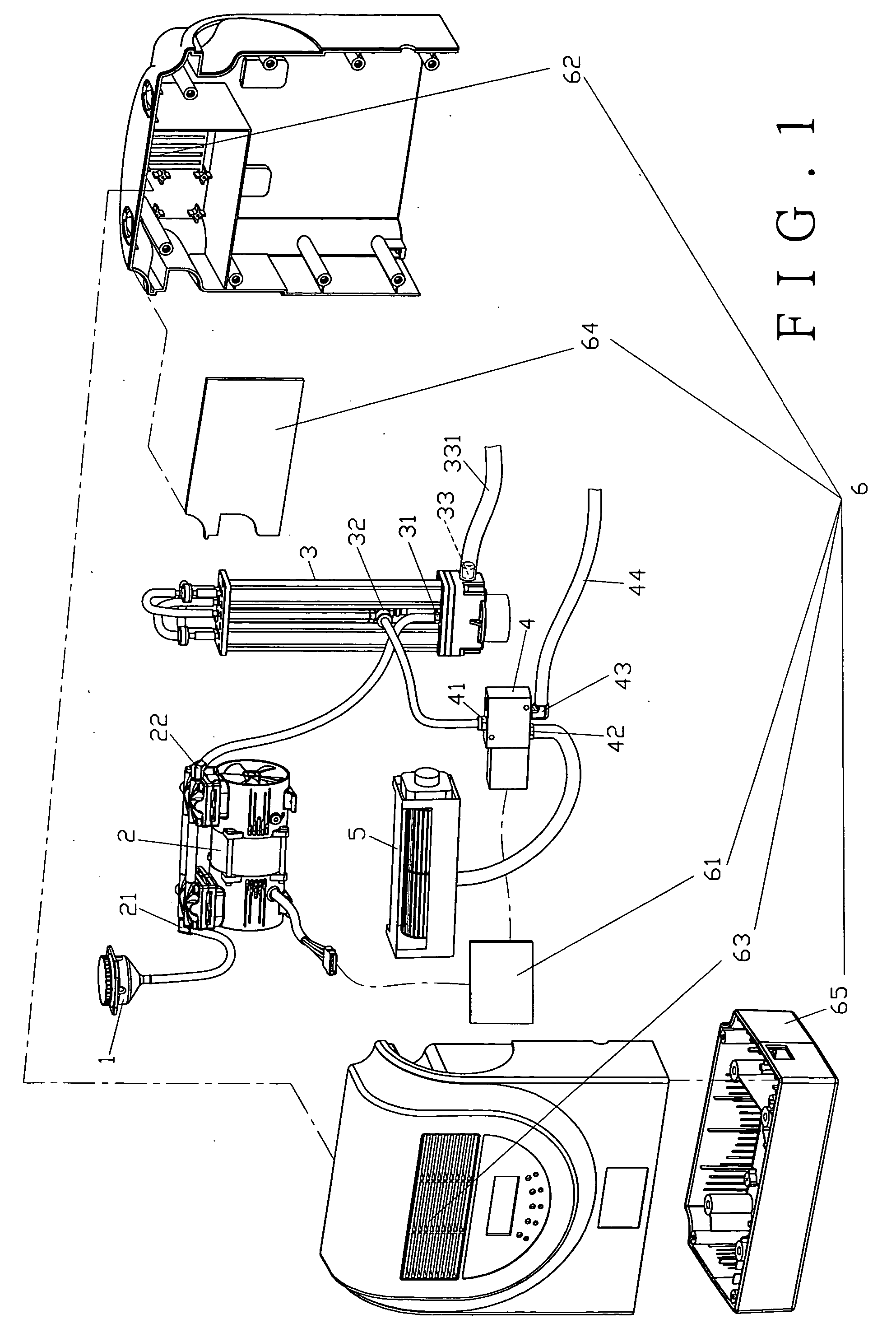
[0009] The present invention, as shown in FIGS. 1˜3, comprises a filter 1, a compressor 2, an oxygen maker 3, an electromagnetic valve 4, and a fan 5, and all of which are securely mounted in a case 6.

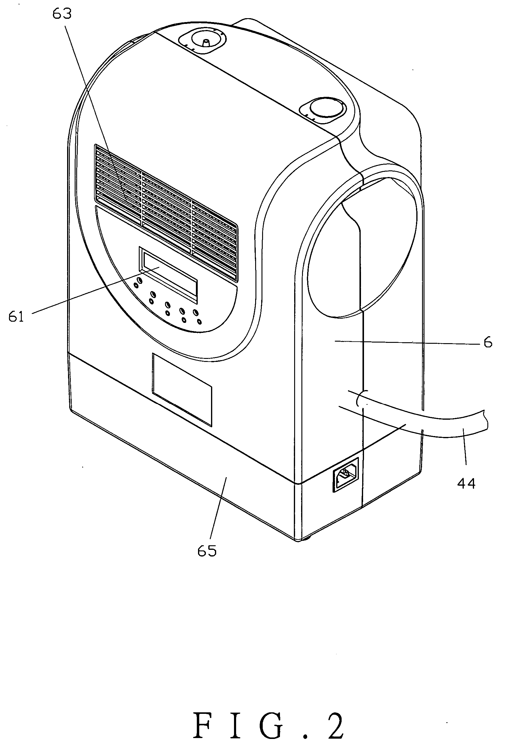
[0010] The case 6 comprises a control panel 61, an inlet vent 62 on the rear plate of the case 6, an outlet vent 63 on the front plate of the case 6, a filtering member 64 next to the inlet vent 62, and a base 65 at the bottom of the case 6. The filtering member 64 is to filter any germs in the air, and it can be an anion filter, high particulate arrestance (HEPA) or Photocatalyst material. The control panel 61 is to activate the compressor 2 and switch the electromagnetic valve 4.

[0011] The compressor 2 comprises an air inlet 21 and an air outlet 22. The air inlet 21 is connected to the filter 1 which corresponds to the inlet vent 62 and the filtering member 64 of the case 6, while the air outlet 22 is connected to the oxygen maker 3.

[0012] The oxygen maker 3 comprises an air inlet...


PUM


Abstract

An air purifier includes a filter, a compressor, an oxygen maker, an electromagnetic valve and a fan, and all of which are mounted in a case. The case has an inlet vent, an outlet vent, and a filtering member next to the outlet vent. The compressor comprises an air inlet and an air outlet. The air inlet of the compressor is connected to the filter, while the air outlet is connected to the oxygen maker. The oxygen maker comprises an air inlet connected to the air outlet of the compressor, an oxygen outlet connected to the electromagnetic valve, and a nitrogen outlet. The electromagnetic valve is connected to the fan. The fan is secured next to the outlet vent of the fan.

Description

FIELD OF THE INVENTION [0001] This invention relates to an air purifier, and more particularly to a purifier to produce oxygen and filter odors and germs in the air. BACKGROUND OF THE INVENTION [0002] Conventional air purifiers are generally in two categories. One is indoor type while the other is window type. The indoor type is placed at a comer in the room, which not only provides purified air but also exhausts waste gas. The window type expels exhaust to the outdoor, but it can't produce enough purified air for indoor use due to its structure. SUMMARY OF THE INVENTION [0003] It is the primary objective of the present invention to provide an air purifier, which is able to produce purified air in a continuous method. [0004] It is another objective of the present invention to provide the air purifier, which eliminates odors thoroughly.BRIEF DESCRIPTION OF THE DRAWINGS [0005]FIG. 1 is an exploded view of the present invention; [0006]FIG. 2 is a perspective view of the present inventi...

Claims


Application Information

Patent Timeline
IPC IPC(8): B01D46/00F24F8/60F24F8/80
CPCA61L9/16A62B11/00C01B13/0229C01B2210/0046F24F3/16F24F2003/1692F24F8/60F24F8/80
Inventor HUANG, SHAO-SHIH
Owner HUANG SHAO SHIH
Why Eureka
Try Eureka