Pulsed mass flow measurement system and method

a mass flow and measurement system technology, applied in the direction of liquid/fluent solid measurement, instruments, coatings, etc., can solve the problem of slow flow sensor and achieve the effect of high repeatability and precise quantities

Inactive Publication Date: 2006-06-22
MKS INSTR INC
View PDF11 Cites 57 Cited by
  • Summary
  • Abstract
  • Description
  • Claims
  • Application Information

AI Technical Summary

Benefits of technology

[0010] Among other aspects and advantages, the present disclosure provides a new and improved system and method for measuring pulsed mass flow of precursor gases into semiconductor processing chambers. The mass flow measurement system and method actually measures

Problems solved by technology

Typically the flow sensor is slow com

Method used


Image

  • Pulsed mass flow measurement system and method
  • Pulsed mass flow measurement system and method
  • Pulsed mass flow measurement system and method

Examples


Embodiment Construction

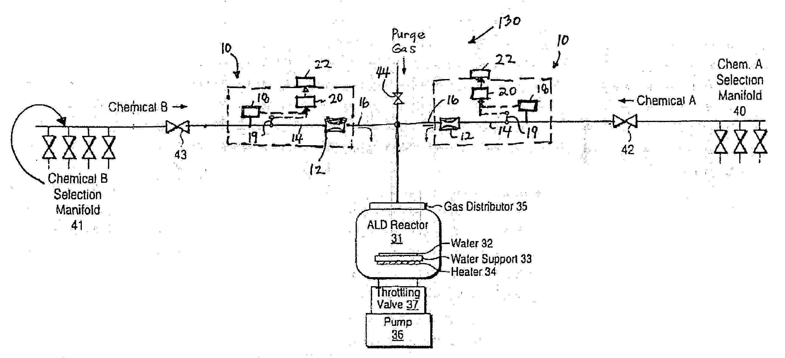
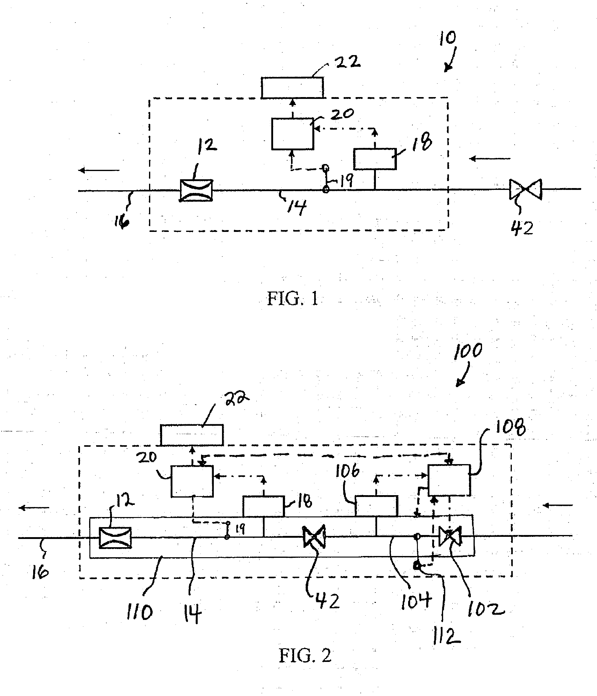
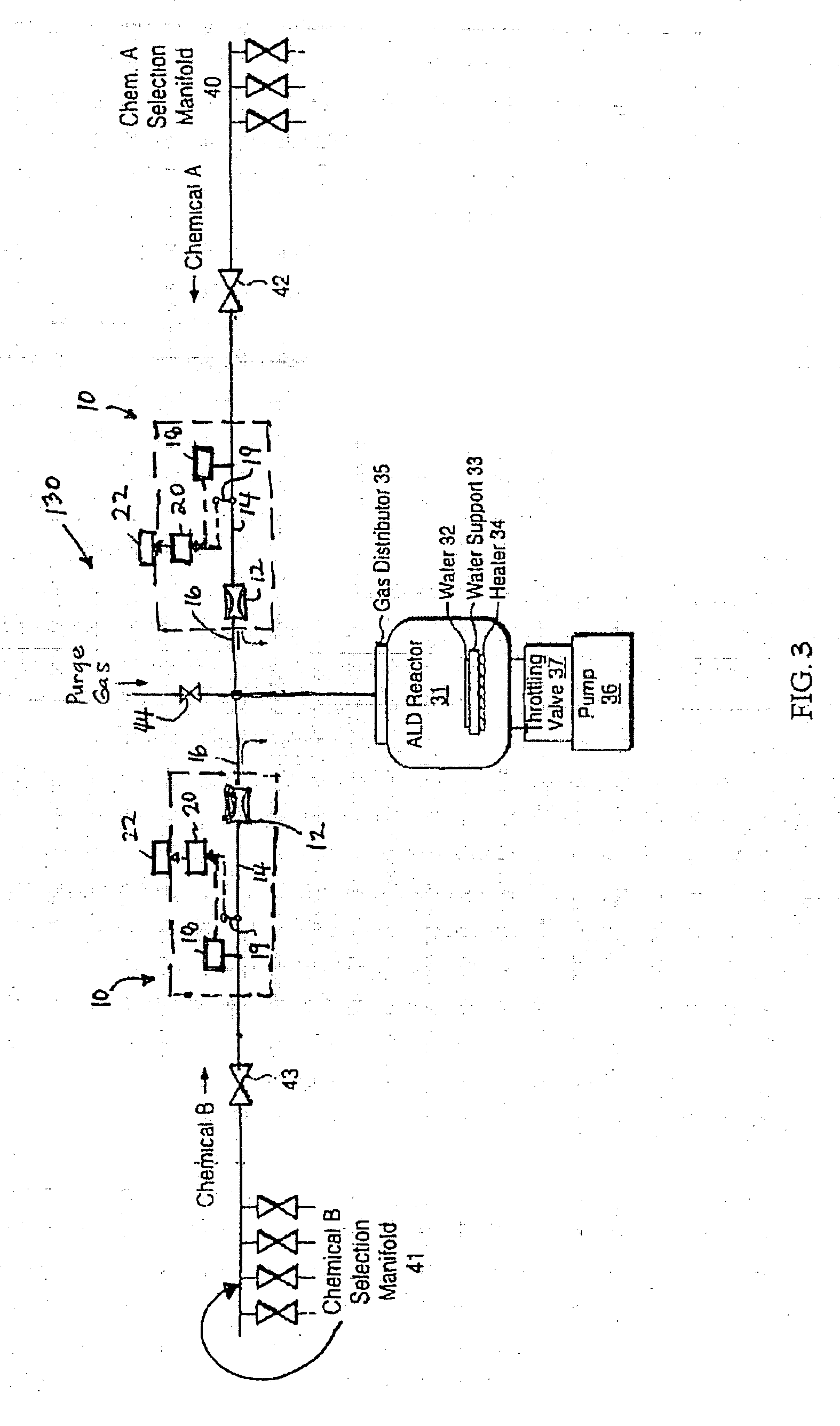
[0020] Referring to FIG. 1, the present disclosure provides an exemplary embodiment of a mass flow measurement system 10 constructed in accordance with the present invention. The system 10 is particularly intended for delivering contaminant-free, precisely metered quantities of process gases to semiconductor process chambers. The mass flow measurement system 10 actually measures the amount of material (mass) flowing into the process chamber. In addition, the system 10 provides highly repeatable and precise quantities of gaseous mass for use in semiconductor manufacturing processes, such as atomic layer deposition (ALD) processes. Prior to describing the system 10 of the present disclosure, however, an example of a semiconductor manufacturing apparatus is first described to provide background information.

[0021]FIG. 7 is a schematic illustration of an exemplary embodiment of an atomic layer deposition system 30 constructed in accordance with the prior art. The system 30 includes a pr...


PUM

PropertyMeasurementUnit
Timeaaaaaaaaaa
Temperatureaaaaaaaaaa
Pressureaaaaaaaaaa

Abstract

A system for measuring a pulsed mass flow rate of gas passing from an upstream source of gas to a downstream process chamber through an on/off type valve of the source of gas. The system includes a passageway for connecting the source of gas to the process chamber, a flow restrictor device dividing the passageway into an upstream portion and a downstream portion, a pressure transducer providing measurements of pressure within the upstream portion of the passageway, a temperature probe providing measurements of temperature within the upstream portion of the passageway, and a CPU connected to the pressure transducer and the temperature probe. The CPU is programmed to receive pressure measurements from the pressure transducer, temperature measurements from the temperature probe, and calculate a mass flow rate through the passageway using the pressure measurements and the temperature measurements.

Description

CROSS-REFERENCE TO RELATED APPLICATIONS [0001] The present application is related to co-pending application Ser. No. ______, filed on _ (attorney docket number MKS-147), and co-pending application Ser. No. 10 / 822,358, filed on Apr. 12, 2004 (attorney docket number MKS-143), both of which are assigned to the assignee of the present application and incorporated herein by reference.FIELD OF THE INVENTION [0002] The present disclosure relates generally to semiconductor manufacturing equipment and, more particularly, to systems and methods for delivering precise quantities of process gases to semiconductor processing chambers. Even more particularly, the present disclosure relates to a system and method for measuring pulsed mass flow of precursor gases into semiconductor processing chambers. BACKGROUND OF THE DISCLOSURE [0003] The manufacture or fabrication of semiconductor devices often requires the careful synchronization and precisely measured delivery of as many as a dozen gases to a...

Claims


Application Information

Patent Timeline
IPC IPC(8): C23C16/00
CPCG01F1/363G01F1/72G01F1/88
Inventor CLARK, WILLIAM R.
Owner MKS INSTR INC
Why Eureka
Try Eureka