Composite motor stator

a stator and composite technology, applied in the direction of machines/engines, liquid fuel engines, rotary piston liquid engines, etc., can solve the problems of stress and heat generated by the movement of the rotor within the stator, rapid degradation of the elastomer, mechanical properties

Inactive Publication Date: 2006-06-22
HALLIBURTON ENERGY SERVICES INC
View PDF15 Cites 21 Cited by
  • Summary
  • Abstract
  • Description
  • Claims
  • Application Information

AI Technical Summary

Problems solved by technology

One drawback in such motors is the stress and heat generated by the movement of the rotor within the stator.
This increased temperature causes rapid degradation of the elastomer.
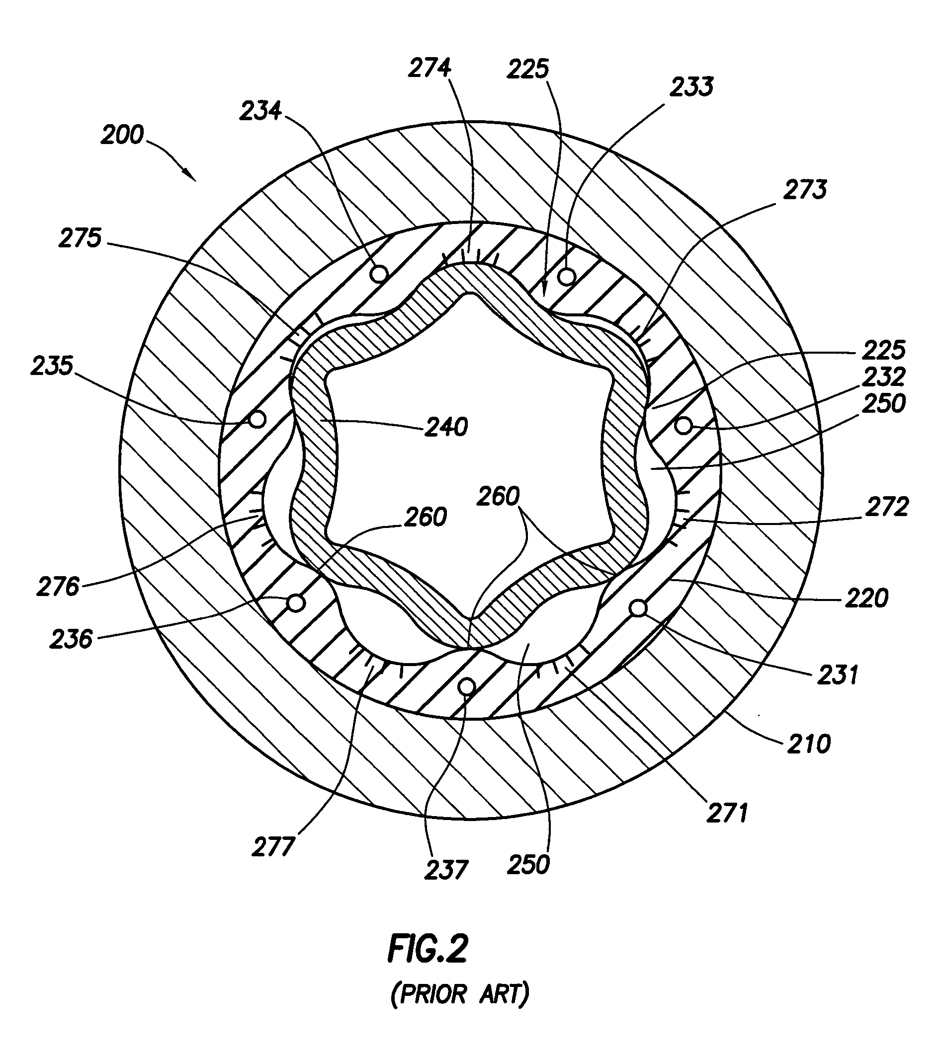
Also, the elevated temperature changes the mechanical properties of the rubber, weakening the stator lobe as a structural member and leading to cracking and tearing of sections 231-237, as well as portions 271-277 of the rubber at the lobe crests.
The cracking and tearing of the elastomer that comprises the stator results in fluid leakage, leading to impaired sealing and reduced motor power.
If severe enough, the cracking and tearing results in “chunking” of the rubber, potentially clogging of downstream parts such as fluid exit nozzles located on the face of the drill bit.
Another undesirable phenomenon that occurs to the motor downhole is uneven bending wear to the rubber.
Complex directional drilling programs may require severe drilling turns.
Alternately, an inexperienced or unfortunate driller may inadvertently make a series of severe turns.
This uneven pressure can lead to further cracking and tearing of the elastomer.
This approach promises a longer life motor, in that rubber degeneration in the motor can cause reduced performance and failure of the motor.
The problems of motor failure are most severe when the motor must be replaced during the drilling program.
This is difficult enough for a shallow well but f

Method used


Image

  • Composite motor stator
  • Composite motor stator
  • Composite motor stator

Examples


Embodiment Construction

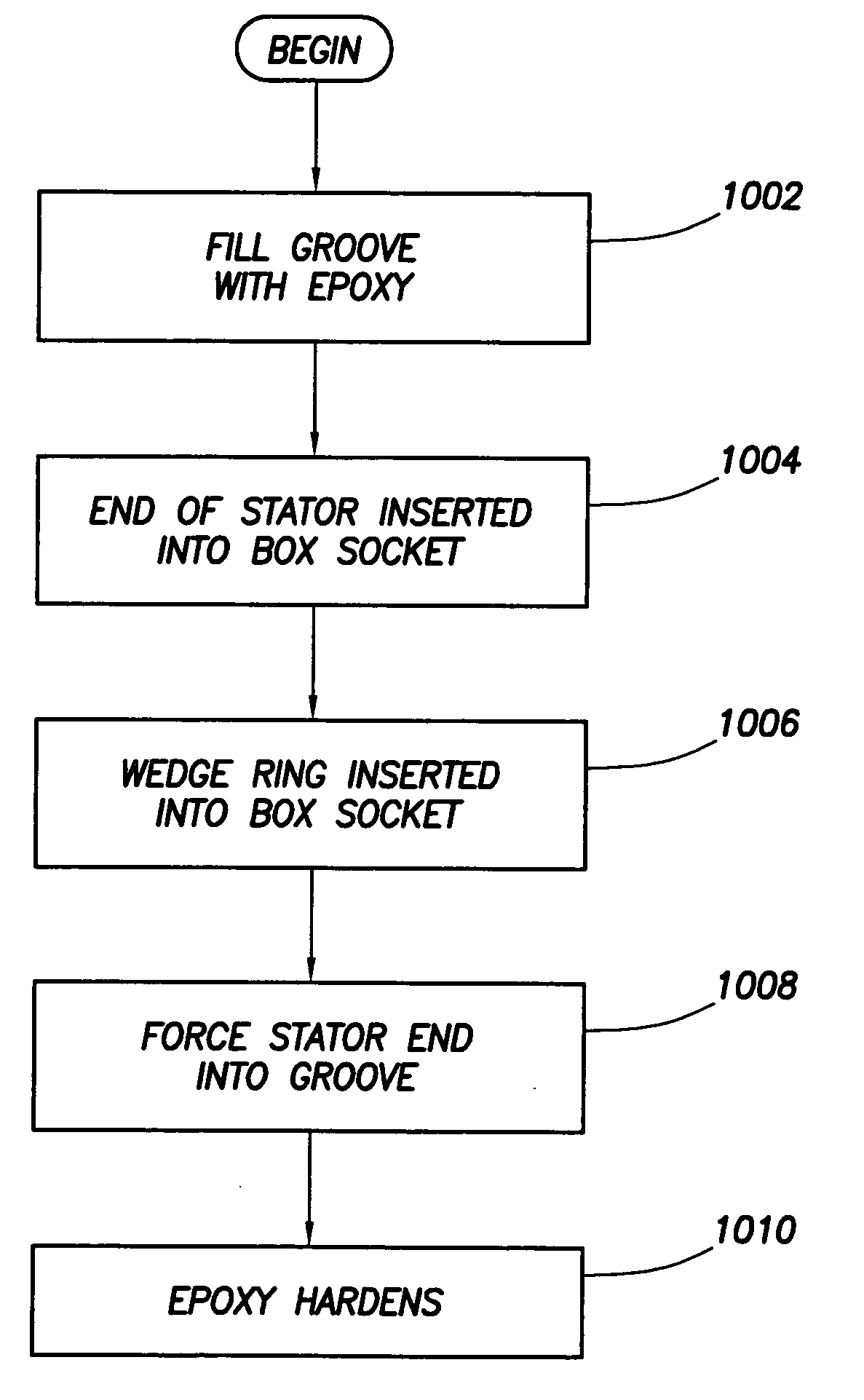
[0027] A Moineau motor stator according to the invention is formed from a composite material and includes lobes formed along the inner diameter of the stator. An elastomeric lining of constant thickness may be applied to the inner diameter of the composite stator. A metal-to-composite box connection is applied to one or both ends of the stator to provide an interface to steel pipelines uphole of the motor and other components. A novel method allowing the economic manufacture of such a composite stator is also disclosed.

[0028]FIG. 3 is a cut-away top-view of a Moineau-style motor 300 manufactured in accordance with an embodiment of the invention. A composite stator 320 has an inner profile 350 and an outer profile 355. Attached to stator 320 is an elastomeric layer 330. As shown, a rotor 310 inserted in the stator 320 has multiple helical lobes. Rotor 310 may be solid or hollow, and may be made from any suitable material including steel. The rotor and elastomeric layer 330 engage at...


PUM

PropertyMeasurementUnit
Fractionaaaaaaaaaa
Lengthaaaaaaaaaa
Thicknessaaaaaaaaaa

Abstract

A hollow stator for a Moineau-style motor is constructed from a composite material such as fiberglass or graphite. A series of lobes arranged along its inner surface corresponds to the external lobes of a rotor inserted in the stator, and enables use of a constant width elastomer layer between the stator and the rotor. The composite stator includes a pair of box socket interface members at its ends to enable the stator to be attached to other components such as pipeline sections.

Description

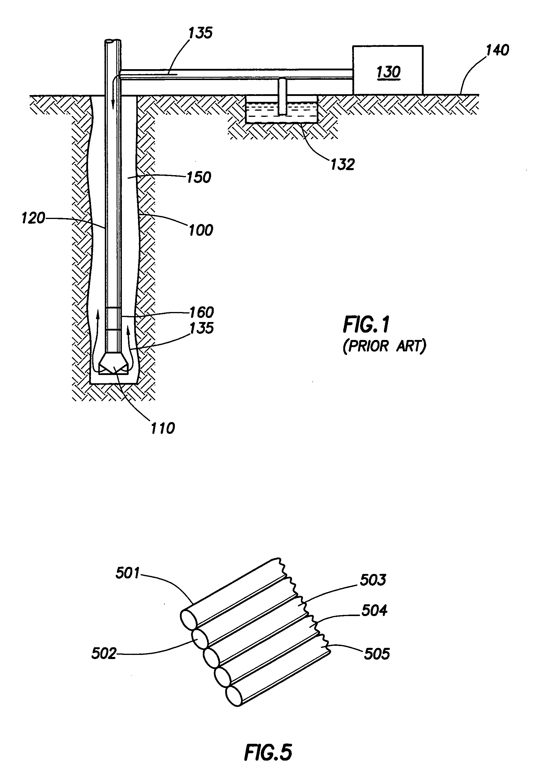
CROSS-REFERENCE TO RELATED APPLICATIONS [0001] Not Applicable. STATEMENT REGARDING FEDERALLY SPONSORED RESEARCH OR DEVELOPMENT [0002] Not Applicable. BACKGROUND OF THE INVENTION [0003] Referring to FIG. 1, in drilling a borehole 100 through a rock formation, such as for the recovery of oil, it is conventional practice to connect a drill bit 110 on the lower end of an assembly of drill pipe sections that are connected end-to-end so as to form a drill string 120. The drill string 120 is rotated and advanced downward, causing the drill bit to cut through the underground rock formation. A pump 130 on the surface 140 typically suctions drilling fluid (also known as drilling mud), represented by arrows 135, from a mud pit 132 and forces it down through a passage in the center of the drill string 120. The drilling fluid then exits the face of the drill bit 110, in the process cooling the face of the drill bit. The drilling mud returns to the surface 150 by an annulus located between the bo...

Claims


Application Information

Patent Timeline
IPC IPC(8): E21B4/00
CPCE21B4/02F04C2/1075F05C2203/02F05C2203/0808F05C2253/16
Inventor BOTTOS, RICHARD D.
Owner HALLIBURTON ENERGY SERVICES INC
Why Eureka
Try Eureka