
Electric oven

a technology of electric oven and heat transfer efficiency, which is applied in the field of electric oven, can solve the problems of low heat transfer efficiency of lower heater, long cooking time, and inability to transfer the heater, and achieve the effect of improving heat transfer efficiency and high heat transfer efficiency of electric oven

Inactive Publication Date: 2006-06-22
SAMSUNG ELECTRONICS CO LTD
View PDF1 Cites 35 Cited by
  • Summary
  • Abstract
  • Description
  • Claims
  • Application Information

AI Technical Summary

Benefits of technology

[0007] Therefore, the present invention has been made in order to solve the above problems, and it is an aspect of the invention to provide an electric oven which can ensure high heat transfer efficiency from lower heaters to a cooking chamber, resulting in an improved heat efficiency of the electric oven.
[0008] It is another aspect of the invention to provide an electric oven which can ensure fast, effective heat transfer from lower heaters to a cooking chamber, resulting in a reduced cooking time.
[0009] It is yet another aspect of the invention to provide an electric oven which can ensure uniform temperature distribution in the lower region of an inner case, enabling even cooking of food.

Problems solved by technology

However, the above described conventional electric oven has a drawback in that the lower heater exhibits a low heat transfer efficiency since it is mounted outside the inner casing and thus part of the heat generated by the lower heater is not transferred into the cooking chamber.
Such conductive heating, however, tends to lengthen cooking time since it involves slow heat transfer.
Furthermore, this makes a temperature distribution in a lower region of the inner casing vary depending on the shape of the lower heater, resulting in uneven cooking of the food placed in the cooking chamber.

Method used


Image

  • Electric oven
  • Electric oven
  • Electric oven

Examples


Embodiment Construction

[0020] Reference will now be made in detail to an illustrative, non-limiting embodiment of the present invention, examples of which are illustrated in the accompanying drawings, wherein like reference numerals refer to like elements throughout. The exemplary embodiment is described below to explain the present invention by referring to the figures.

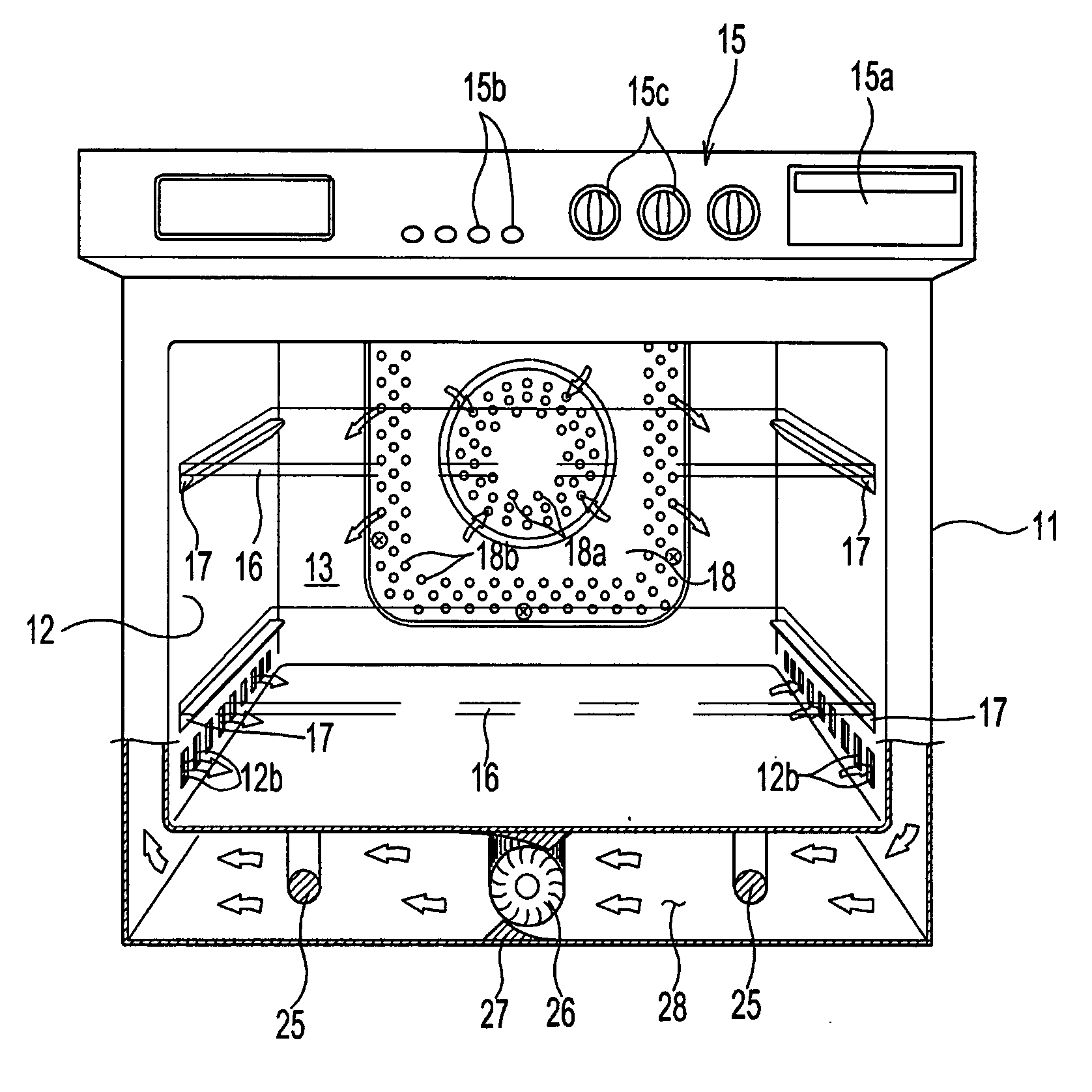
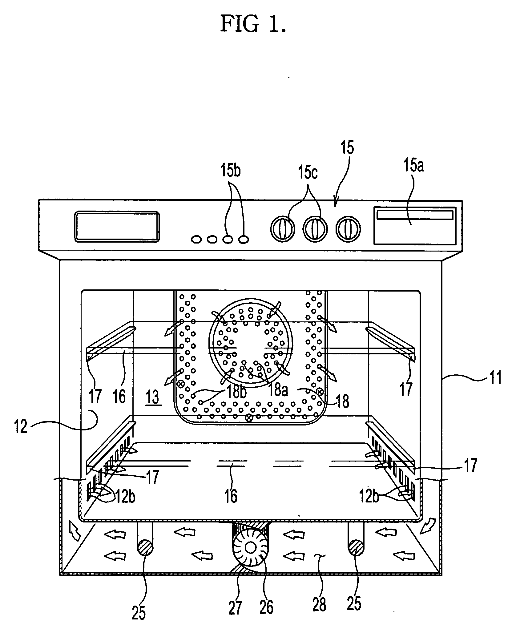
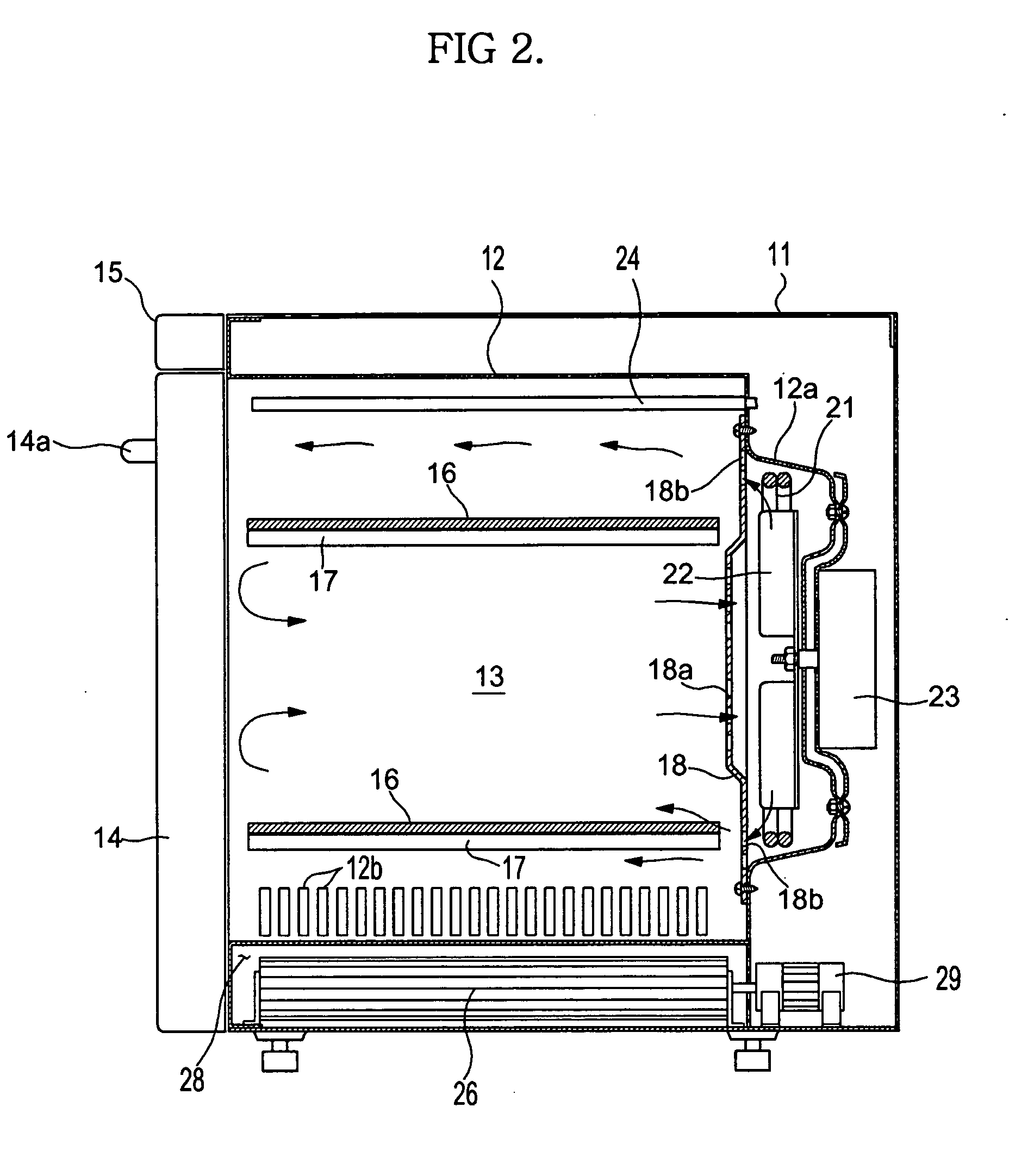
[0021]FIGS. 1 and 2 are views illustrating an electric oven consistent with an exemplary embodiment of the present invention. As shown in FIGS. 1 and 2, the electric oven comprises an outer case 11 defining the appearance of the electric oven and made of, for example, an iron plate, and an inner case 12 inwardly spaced apart inward from the outer case 11 by a predetermined distance. The inner case 12 internally defines a cooking chamber 13 that receives food to be cooked. The outer and inner cases 11 and 12 have an opening at a front portion thereof to allow the user to put food into or take it out of the cooking chamber 13. A door 14 is ...


PUM


Abstract

An electric oven including lower heaters arranged under a cooking chamber thereof. The electric oven includes an outer case defining the appearance of the electric oven, an inner case inwardly spaced apart from the outer case by a predetermined distance, and lower heaters arranged between bottom walls of the outer and inner cases. The inner case internally defines a cooking chamber, and a blowing fan is installed near the lower heaters to circulate air existing in the cooking chamber toward the lower heaters. With the electric oven configured as stated above, heat generated by the lower heaters is transferred to the cooking chamber in the form of conductive heat and convective heat, resulting in fast and efficient heat transfer and even cooking of food.

Description

CROSS-REFERENCE TO RELATED APPLICATION [0001] This application claims priority from Korean Patent Application No. 2004-109735, filed on Dec. 21, 2004 in the Korean Intellectual Property Office, the disclosure of which is incorporated herein by reference. BACKGROUND OF THE INVENTION [0002] 1. Field of the Invention [0003] The present invention relates to an electric oven and, more particularly, to a heater to heat a lower region of a cooking chamber. [0004] 2. Description of the Related Art [0005] Electric ovens are appliances used for baking or roasting food by circulating air existing in a cooking chamber to heaters, causing the air, heated by the heaters, to heat the interior of the cooking chamber. An example of such conventional electric ovens is disclosed in Korean Patent Laid-open Publication No. 2004-0067381. The disclosed conventional electric oven comprises an outer casing defining the appearance of the electric oven, an inner casing mounted in the outer casing and internal...

Claims


Application Information

Patent Timeline
IPC IPC(8): A21B1/22A21B1/00F27D11/00
CPCF24C15/325F24C7/04F24C7/06
Inventor SEUK OH, KEUN
Owner SAMSUNG ELECTRONICS CO LTD
Learn More