Turboelectric arresting gear

a technology of arresting gear and rotating rods, which is applied in the direction of arresting gear, alighting gear, and ground installations, can solve the problems of sudden deceleration or “jerk”, high stress generation in the purchase cable, the tail hook and the aircraft frame, and the problem of hydraulic energy absorbing systems, etc. problem, to achieve the effect of slowing down the landing aircraft and constant tension

Inactive Publication Date: 2006-06-22
GENERAL ATOMICS
View PDF29 Cites 16 Cited by
  • Summary
  • Abstract
  • Description
  • Claims
  • Application Information

AI Technical Summary

Benefits of technology

[0011] In accordance with the present invention, the arresting engine includes an energy-dissipating fluid turbine, such as a water twister, that is mounted on the shaft to apply a torque on the shaft that can decelerate the rotating shaft. To complement the energy-dissipating fluid turbine, an electric motor is coupled to the shaft for creating a decelerating torque on the shaft when the line is pulled by the moving object. For aircraft landing applications, an electric motor control system is provided that is configured to cause the electric motor to produce an accelerating torque on the shaft upon ini

Problems solved by technology

Primary among these drawbacks is the generation of a high stress in the purchase cable, the pendant, the tail hook and the aircraft frame.
This high stress causes a sudden deceleration or “jerk” that is imparted on the decelerating object immediately after the pendant engages the arresting hook.
In addition to the problems described above regarding relatively heavy aircraft, currently available hydraulic energy absorbing systems are also problematic for relatively light aircraft w

Method used


Image

  • Turboelectric arresting gear
  • Turboelectric arresting gear
  • Turboelectric arresting gear

Examples


Embodiment Construction

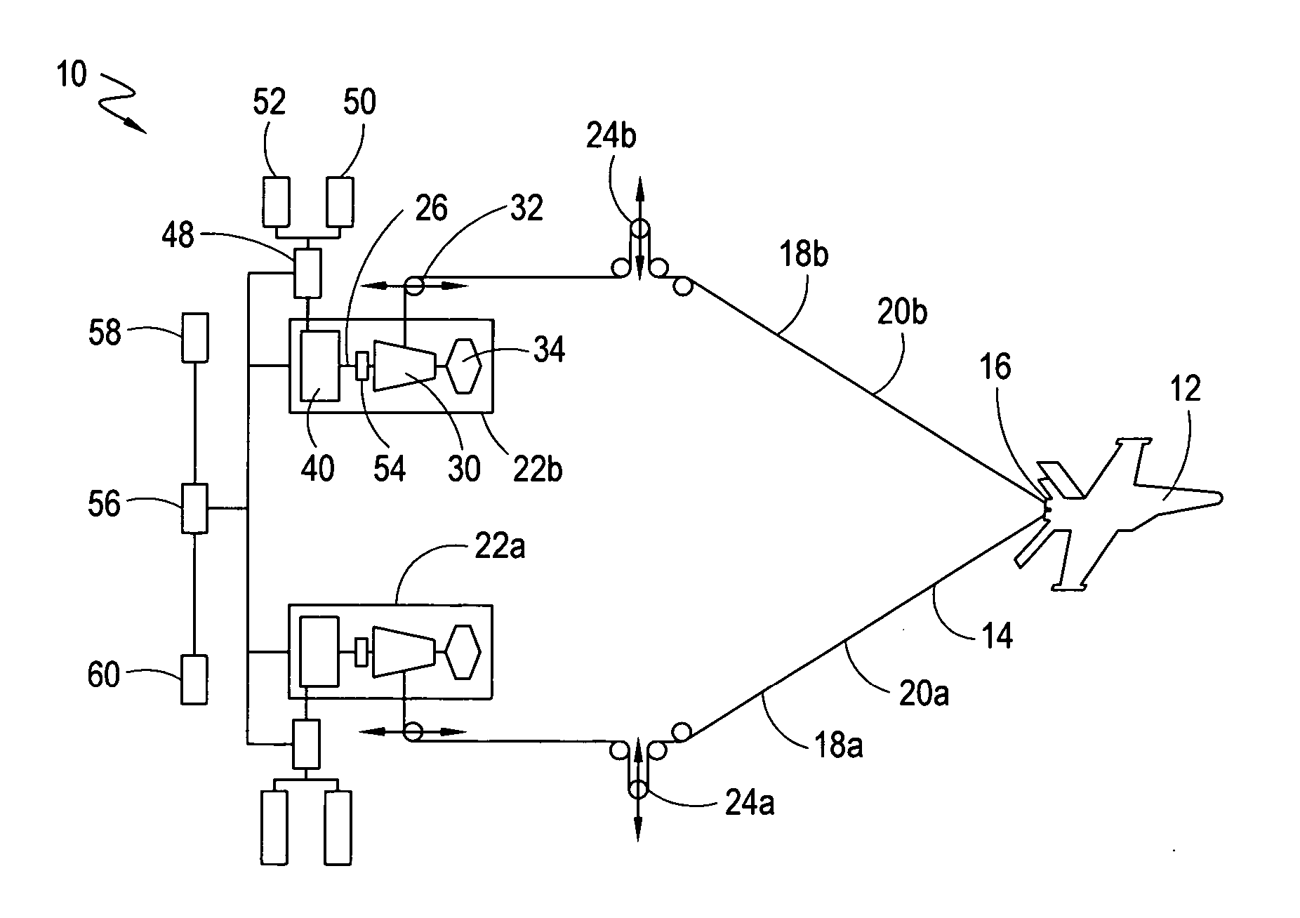
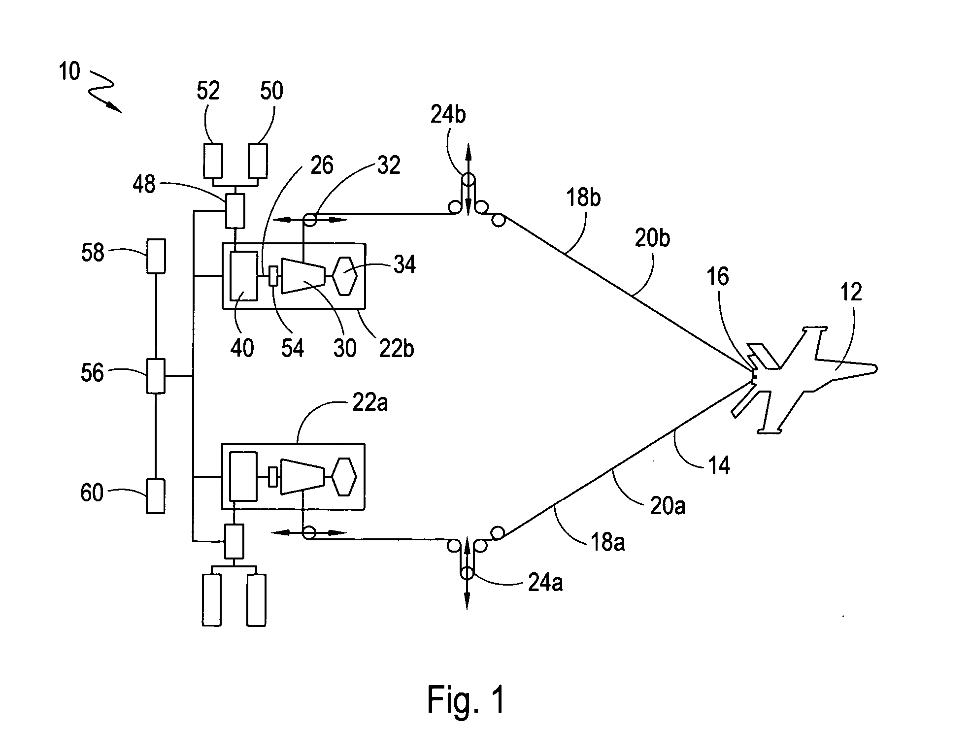
[0016] Referring to FIG. 1, an arresting gear in accordance with the present invention is shown and generally designated 10. In functional overview, the arresting gear 10 is designed to quickly decelerate and arrest a landing aircraft 12 using a relatively short runway. The arresting gear 10 is typically mounted on the ground or the deck of a ship to decelerate and arrest an aircraft 12 using a relatively short runway. Although the arresting gear 10 is shown configured for an application in which an aircraft is to be decelerated and arrested, those skilled in the pertinent art will quickly appreciate that the arresting gear 10 shown can be adapted to decelerate other moving objects, including but not limited to, elevator platforms for freight elevators and for use in high-rise structures.

[0017]FIG. 1 shows the arresting gear 10 includes a cross-deck pendant 14 that is operationally suspended over and spans the width of the runway. Those skilled in the pertinent art will appreciate ...


PUM


Abstract

An arresting gear for quickly decelerating a moving object includes an elongated shaft that defines a rotation axis. A tapered drum that is wound with a purchase cable is mounted on the shaft for rotation about the axis. The drum and the shaft are rotated during the pay out of cable from the drum as the moving object engages and then pulls on the cable. The arresting gear includes an energy-dissipating fluid turbine, such as a water twister, that is mounted on the shaft to apply a torque on the shaft that acts to decelerate the rotating shaft. To complement the energy-dissipating fluid turbine, an electric motor is coupled to the shaft for creating a decelerating torque on the shaft. An electric motor control system is configured to use motor rotation feedback from the electric motor to pay out the cable from the drum at a substantially constant tension.

Description

FIELD OF THE INVENTION [0001] The present invention pertains generally to arresting gear for decelerating a moving object. More particularly, the present invention pertains to arresting gear for smoothly decelerating objects such as aircraft and elevators. The present invention is particularly, but not exclusively, useful as a system for decelerating a moving object that is operable for a wide range of object types, weights and speeds. BACKGROUND OF THE INVENTION [0002] Present-day aircraft normally require the use of runways that are approximately 5,000 to 8,000 feet long in order to land safely. In some applications, however, it is desirable to stop these same aircraft within a few hundred feet. This feat is typically accomplished using arresting gear that can bring a moving object to a controlled stop by absorbing and dispelling energy developed by the moving object. For the case of a landing aircraft, an arresting gear system typically includes a pendant that is suspended over a...

Claims


Application Information

Patent Timeline
IPC IPC(8): B64F1/02
CPCB64F1/02B64F1/029
Inventor HOLLAND, LEO D.RODRIGUEZ, CARMELO
Owner GENERAL ATOMICS
Why Eureka
Try Eureka