Pinch detection device and opening/closing device

a detection device and a technology for opening/closing devices, applied in the direction of roofs, wing accessories, transportation and packaging, etc., can solve problems such as error detection, and achieve the effects of enhancing reliability, large output signal, and enhancing reliability

Inactive Publication Date: 2006-06-22
PANASONIC CORP
View PDF2 Cites 8 Cited by
  • Summary
  • Abstract
  • Description
  • Claims
  • Application Information

AI Technical Summary

Benefits of technology

[0008] The pressure sensor has a flexible piezoelectric sensor. Under a situation where a contact-type pressure-sensitive switch comprising a plurality of mutually-opposing electrodes is used as the pressure sensor and disposed along the trunk lid, if the trunk lid has a bent section, the electrodes contact each other at that bent section, thereby causing erroneous detection. In contrast, the piezoelectric sensor has no contacts. Even when the piezoelectric sensor is disposed along bent areas, the sensor can detect occurrence of pinching without involvement of occurrence of a detection error, whereby enhanced reliability is achieved.
[0009] The pressure sensor has a nonlinear flexible member whose displacement in response to load is nonlinear. The piezoelectric sensor is disposed adjacent to the nonlinear flexible member. For instance, even when an object is pinched when the closing speed of the trunk lid is slow, the nonlinear flexible member is quickly deformed as a result of the pressing load exerted on the pressure sensor by the object having reached a predetermined value or more, and the adjacently-disposed piezoelectric sensors also undergo sudden deformation, thereby outputting a large output signal. As a result, occurrence of pinching can be determined by the determination means, and reliability concerning detection of pinch is greatly enhanced.
[0010] The determination means determines whether or not the object maintains contact with the object, on the basis of the signal output from the piezoelectric sensor. For instance, when the object is determined to maintain contact with the piezoelectric sensor, control for inhibiting closing of the trunk lid becomes feasible, thereby resulting in enhanced reliability.
[0011] The pressure sensor has a cushioning section which can be compressed by the pressure stemming from the pinched object. Even when occurrence of pinching has been detected, the cushioning section is compressed until movement of the trunk lid is reversely moved. Therefore, an increase in pinching load applied to the object can be prevented, to thus diminish stress or damage inflicted on the pinched object.
[0012] Moreover, the present invention further comprises the above-described pinching detection apparatus, drive means for driving the trunk lid, and control means for controlling the drive means so as to release pinching when pinching is determined to have arisen on the basis of the signal output from the determination means. Pinching is released when pinching is determined to have arisen, and hence occurrence of unwanted pinching can be prevented.
[0013] When the trunk lid is closed, the drive means is controlled such that the trunk lid is closed after the trunk lid has once been moved over a predetermined distance in an opening direction. Even when the object has come into contact with the piezoelectric sensor before the trunk lid starts closing, the trunk lid is closed after having once been moved over a predetermined distance in an opening direction. The inertial force of the object having moved in the opening direction is applied to the piezoelectric sensor by means of the closing action, thereby reliably pressing the piezoelectric sensor. Therefore, occurrence of pinching can be reliably detected.

Problems solved by technology

Under a situation where a contact-type pressure-sensitive switch comprising a plurality of mutually-opposing electrodes is used as the pressure sensor and disposed along the trunk lid, if the trunk lid has a bent section, the electrodes contact each other at that bent section, thereby causing erroneous detection.

Method used


Image

  • Pinch detection device and opening/closing device
  • Pinch detection device and opening/closing device
  • Pinch detection device and opening/closing device

Examples


first embodiment

[0028] An invention of a first embodiment will be described by reference to FIGS. 1(a) to 6.

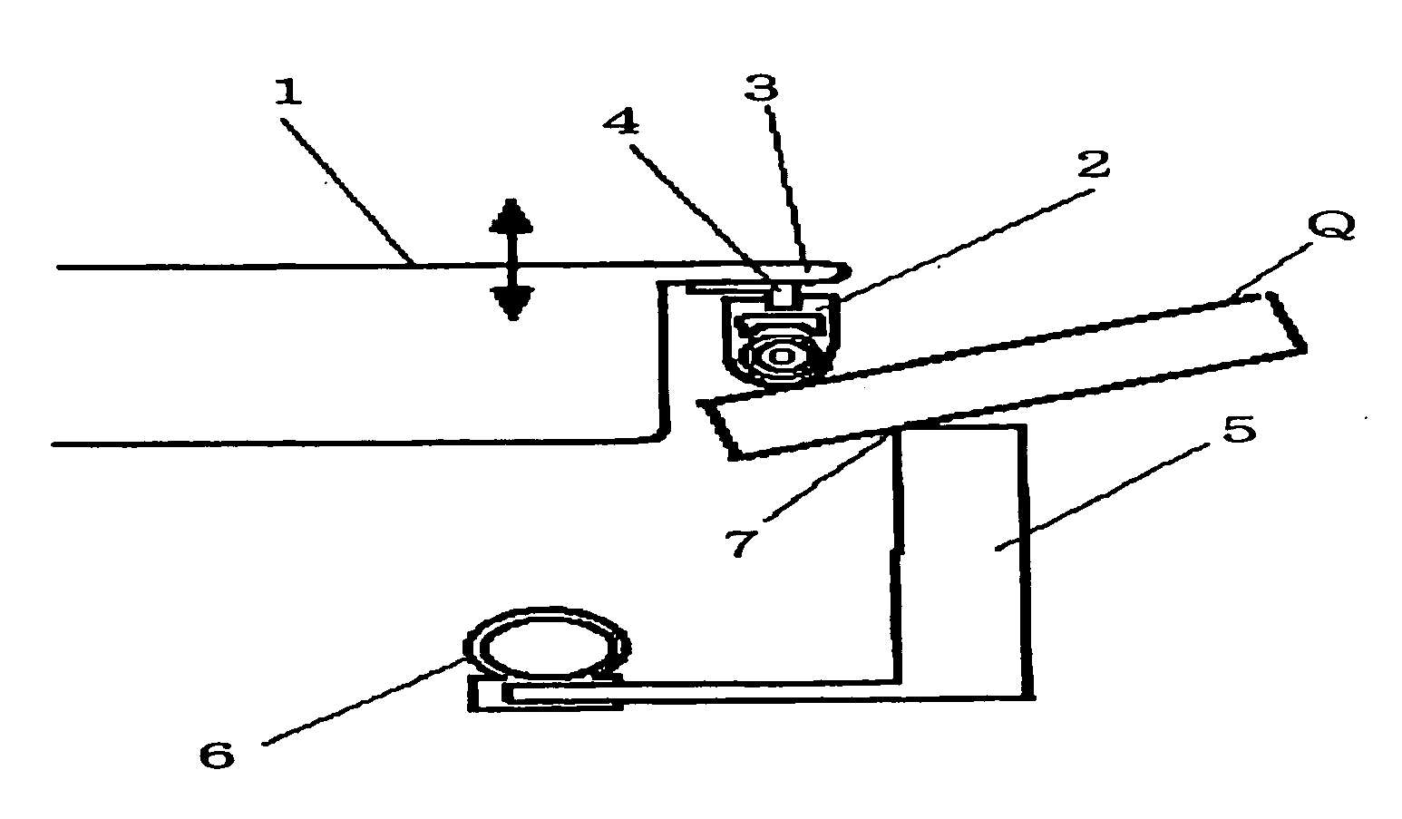
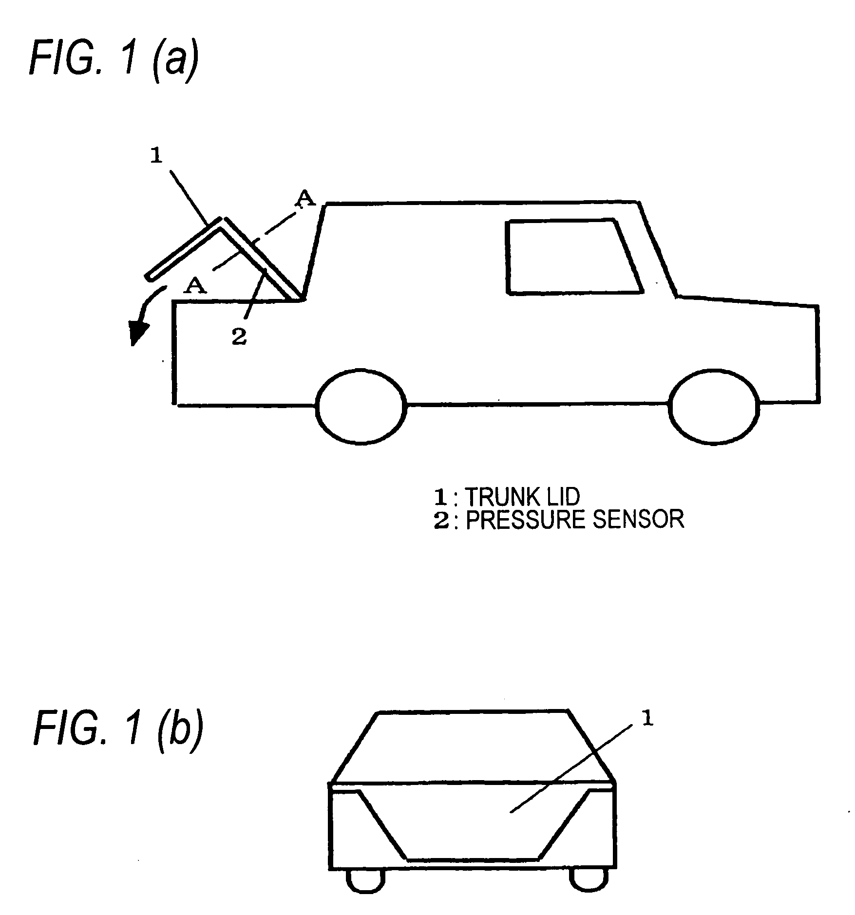
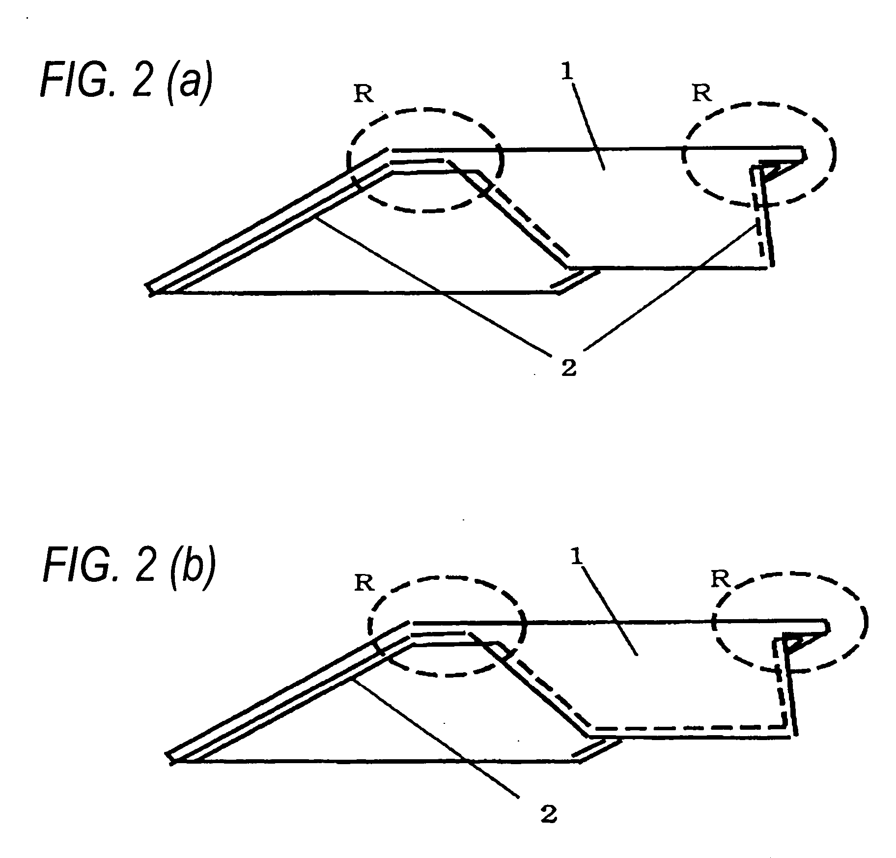
[0029]FIG. 1(a) is an external view of a pinching detection apparatus and an opening / closing apparatus of the invention of the first embodiment as viewed from a lateral direction of a vehicle body (showing a state where a trunk lid is open), and FIG. 1(b) is an external view of the same as viewed from the rear of the vehicle body (showing a state where the trunk lid is closed), both views showing a configuration where a pressure sensor 2 is disposed on a trunk lid 1 of a vehicle is shown. FIG. 2 is external views showing a placement location of the pressure sensor 2 on the trunk lid 1, where the trunk lid 1 is viewed from the interior of the vehicle. FIG. 2(a) shows a state where the pressure sensor 2 is disposed on each of right and left sides of the trunk lid 1, and FIG. 2(b) shows a state where a single pressure sensor 2 is disposed along both the right and left sides and a lower end of t...

second embodiment

[0051] An invention of a second embodiment will be described by reference to FIGS. 7(a) and 7(b). FIGS. 7(a) and 7(b) show cross-sectional views of the pressure sensor 2 of a pinching detection apparatus and the invention of the second embodiment; where FIG. 7(a) shows a state where a predetermined load is not applied on the pressure sensor 2, and FIG. 7(b) shows a state where a load of predetermined value or greater is applied, thereby compressing the pressure sensor 2.

[0052] The second embodiment differs from the first embodiment in that the pressure sensor 2 includes a nonlinear flexible member 8 whose deflection in relation to a load is nonlinear, and in that the piezoelectric sensor 8 is disposed adjacent to the nonlinear flexible member 28. As the nonlinear flexible member 28, there is used, for instance, a strip thin steel or reinforced resin of a convex shape as employed in a convex gage. Such a member has a characteristic of being abruptly deformed concavely when pressing ...

third embodiment

[0055] An invention of a third embodiment will be described hereunder. A difference between the third embodiment and the first and second embodiments lies in that the object maintains contact with the pressure sensor 2 in accordance with a signal output from the piezoelectric sensor 8.

[0056] The operation stemming from the above-described configuration is described by reference to FIG. 8. FIG. 8 is a characteristic view showing a signal V output from a filter section 19 in determination means 16 of the third embodiment and a determination J output from a pinch determination section 20 of the same. In FIG. 6, V and J denote, in this order, vertical axes, and a horizontal axis represents a time “t.” The filter section 19 employs a configuration analogous to those of the first and second embodiments.

[0057] As shown in FIG. 8, when a portion of the pressure sensor 2 of the trunk lid 1 is gripped or released by a hand, a signal component greater than a reference potential V0 and a sign...


PUM

PropertyMeasurementUnit
distanceaaaaaaaaaa
flexibleaaaaaaaaaa
distanceaaaaaaaaaa

Abstract

A pinching detection apparatus having a pressure sensor 2 disposed along the geometry of a trunk lid 1 in a flexible manner, and determination means 16 for detecting that an object is being pinched between a body opening section 7 and the trunk lid 1, in accordance with a signal output from the pressure sensor 2. Since the pressure sensor 2 is disposed along the geometry of the trunk lid 1 in a flexible manner, pinching by the trunk lid 1 can be detected.

Description

FIELD OF THE INVENTION [0001] The present invention relates to a pinching detection apparatus which detects that an object is being pinched between a body opening section of a vehicle, such as an automobile, and a trunk lid, as well as to an opening / closing apparatus. BACKGROUND TECHNIQUE [0002] A related-art pinching detection apparatus has a motor-driven trunk lid and indirectly detects that an object is being pinched between a body opening section and the trunk lid, on the basis of a change in the driven state of the motor which arises when the object has been pinched between the body opening section and the trunk lid (see, e.g., “Introduction of State-of-the-Art Embedded in E65, No. 1, Exterior,” May 7th, 2002, http: / / www.bohp.net / html / event91.htm).].”[0003] However, according to the above-described related-art configuration, occurrence of pinching is detected on the basis of a change in a driven state of a motor; e.g., a change in a drive current supplied to the motor. For this...

Claims


Application Information

Patent Timeline
Patent Type & Authority Applications(United States)
IPC IPC(8): B62D25/10E05F15/12E05F15/00G01L1/16
CPCE05F15/44E05Y2900/548
Inventor OGINO, HIROYUKIUEDA, SHIGEKI
Owner PANASONIC CORP
Why Eureka
Try Eureka