Exposure apparatus, method for producing device, and method for controlling exposure apparatus

a technology of exposure apparatus and producing device, which is applied in the direction of photomechanical apparatus, printing, instruments, etc., can solve the problems of insufficient margin, inconvenience, and difficulty in matching the substrate surface with respect to the image plane of the projection optical system

Inactive Publication Date: 2006-06-22
NIKON CORP
View PDF99 Cites 158 Cited by
  • Summary
  • Abstract
  • Description
  • Claims
  • Application Information

AI Technical Summary

Benefits of technology

[0063] According to the method for controlling the exposure apparatus of the present invention, when the abnormality arises in the exposure apparatus or in the related unit disposed outside the exposure apparatus, and the abnormality is the signal notifying such abnormality that the exposure of the substrate or the like is affected thereby, then the operation is restricted for at least one of the liquid supply mechanism (10), the unit (47, 48) which uses the electric energy as the driving force, and the unit (42, PH) which has the function to suck the gas. Accordingly, it is possible to avoid, for example, the liquid leakage, the electric leakage caused thereby, and the suction of the liquid by the suction unit.

Problems solved by technology

If the depth of focus δ is too narrowed, it is difficult to match the substrate surface with respect to the image plane of the projection optical system.
It is feared that the margin is insufficient during the exposure operation.
In the case of the liquid immersion exposure apparatus, if the liquid for the exposure causes any leakage or any invasion, there is such a possibility that any inconvenience may be caused such that the apparatus and the members undergo, for example, the malfunction, the electric leakage, and the rust due to the liquid.
Further, such a situation makes it impossible to perform the exposure process satisfactorily.

Method used


Image

  • Exposure apparatus, method for producing device, and method for controlling exposure apparatus
  • Exposure apparatus, method for producing device, and method for controlling exposure apparatus
  • Exposure apparatus, method for producing device, and method for controlling exposure apparatus

Examples


first embodiment

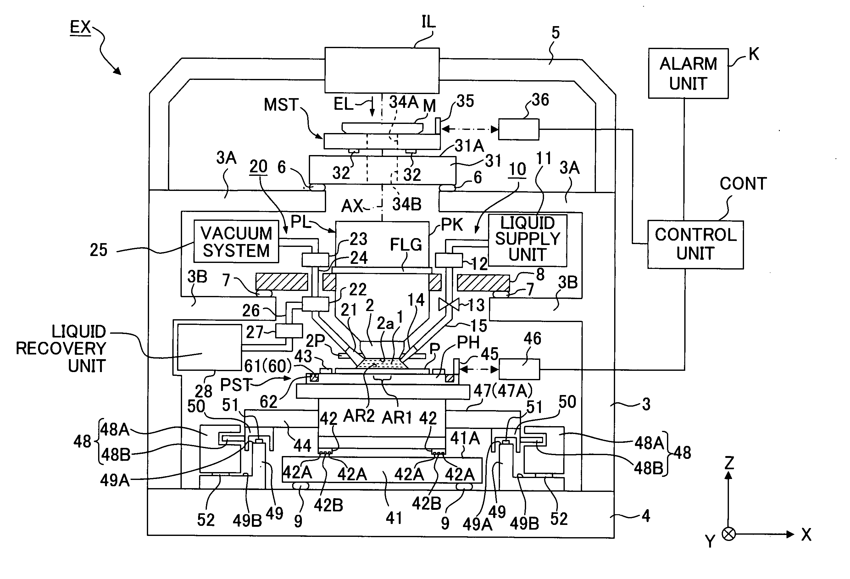
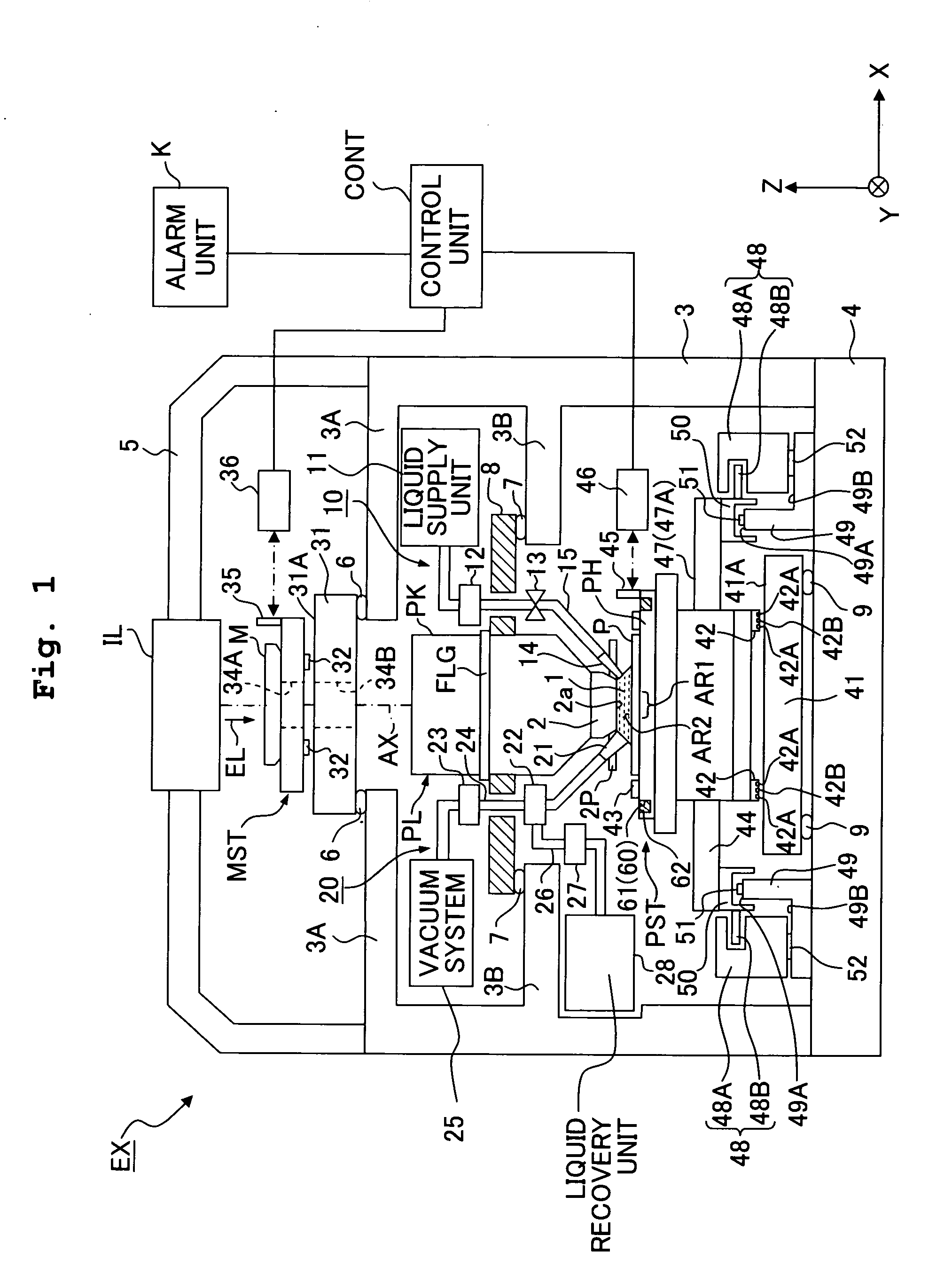
[0089]FIG. 1 shows a schematic arrangement illustrating the exposure apparatus of the present invention. With reference to FIG. 1, an exposure apparatus EX includes a mask stage MST which supports a mask M, a substrate stage PST which supports a substrate P, an illumination optical system IL which illuminates, with an exposure light beam EL, the mask M supported by the mask stage MST, a projection optical system PL which performs projection exposure for the substrate P supported by the substrate stage PST with an image of a pattern of the mask M illuminated with the exposure light beam EL, and a control unit CONT which collectively controls the overall operation of the exposure apparatus EX. An alarm unit K, which generates an alarm when any abnormality arises in relation to the exposure process, is connected to the control unit CONT. The exposure apparatus EX further includes a main column 3 which supports the mask stage MST and the projection optical system PL. The main column 3 i...

second embodiment

[0152] Next, an explanation will be made about the exposure apparatus EX of the present invention. In the following explanation, the constitutive components, which are the same as or equivalent to those of the embodiment described above, are designated by the same reference numerals, any explanation of which will be simplified or omitted. In this embodiment, the leakage of the liquid 1, for example, to the outside of the substrate P or the substrate stage PST (substrate holder PH) is optically detected by using a detector including an optical fiber to execute at least one of the stop of the liquid supply operation by the liquid supply mechanism 10, the stop of the electric power supply to the electric unit, and the stop of the suction operation from the suction port when the leakage or the invasion of the liquid 1 is detected.

[0153] An explanation will be made with reference to FIGS. 6 and 7 about the detection principle of the detector for detecting the leakage of the liquid 1. The...

third embodiment

[0164] Next, an explanation will be made about the exposure apparatus EX of the present invention. In this embodiment, the leakage of the liquid 1 is optically detected by using a detector including a prism (optical element). When the leakage of the liquid 1 is detected, at least one of the stop of the liquid supply operation by the liquid supply mechanism 10, the stop of the electric power supply to the electric unit, and the stop of the suction operation from the suction port is executed.

[0165] An explanation will be made about the detection principle of the detector for detecting the leakage of the liquid 1 with reference to FIGS. 14 and 15. In this embodiment, the prism is used as the detector. FIG. 14 shows a schematic arrangement of the detector 100 based on the use of the prism. With reference to FIG. 14, the detector 100 includes the prism 101, a light-emitting section 102 which is attached to a first surface 101A of the prism 101 and which emits the light with respect to th...


PUM

PropertyMeasurementUnit
refractive indexaaaaaaaaaa
wavelengthaaaaaaaaaa

Abstract

An exposure apparatus (EX) exposes a substrate (P) by projecting an image of a pattern on the substrate (P) via a projection optical system (PL) and a liquid (1). The exposure device (EX) has a liquid supply mechanism (10) which supplies the liquid (1) between the projection optical system (PL) and the substrate (P). The liquid feeding mechanism (10) stops the supply of the liquid (1) when abnormality is detected. This suppresses influence to devices and members in the periphery of the substrate caused by leakage of the liquid forming a liquid immersion area, thereby realizing satisfactory exposure processing.

Description

CROSS-REFERENCE [0001] This application is a Continuation application of International Application No. PCT / JP2004 / 010991 which was filed on Jul. 26, 2004 claiming the conventional priority of Japanese patent Applications No. 2003-281183 filed on Jul. 28, 2003 and No. 2004-045104 filed on Feb. 20, 2004.BACKGROUND OF THE INVENTION [0002] 1. Field of the Invention [0003] The present invention relates to an exposure apparatus for exposing a substrate via a projection optical system and a liquid, a method for producing a device based on the use of the exposure apparatus, and a method for controlling the exposure apparatus. [0004] 2. Description of the Related Art [0005] Semiconductor devices and liquid crystal display devices are produced by means of the so-called photolithography technique in which a pattern formed on a mask is transferred onto a photosensitive substrate. The exposure apparatus, which is used in the photolithography step, includes a mask stage for supporting the mask an...

Claims


Application Information

Patent Timeline
Patent Type & Authority Applications(United States)
IPC IPC(8): G03B27/42G03F7/20
CPCG03F7/70341G03F7/70525G03F7/709G03F7/70858G03F7/70725H01L21/0274G03F7/70866
Inventor MAGOME, NOBUTAKAKOBAYASHI, NAOYUKISAKAKIBARA, YASUYUKITAKAIWA, HIROAKI
Owner NIKON CORP
Why Eureka
Try Eureka