Optical element for an illumination system

an illumination system and optical element technology, applied in the field of optical element for illumination system, can solve the problems of increasing light loss, plurality of optical components, and collecting does not produce an image of the light source in finite space, so as to reduce the number of components and minimize light loss

Inactive Publication Date: 2006-06-22
CARL ZEISS SMT GMBH
View PDF18 Cites 349 Cited by
  • Summary
  • Abstract
  • Description
  • Claims
  • Application Information

AI Technical Summary

Benefits of technology

[0026] The object of the invention is to overcome the disadvantages of the prior art, and in parti...

Problems solved by technology

Therefore, this collector does not produce an image of the light source in finite space.
Since each additional optical element means an increased light loss, in particular, if reflective optics are utilized because of the small wavelengths, the solution proposed in EP-A-1,024,408 has disadvant...

Method used


Image

  • Optical element for an illumination system
  • Optical element for an illumination system
  • Optical element for an illumination system

Examples


Embodiment Construction

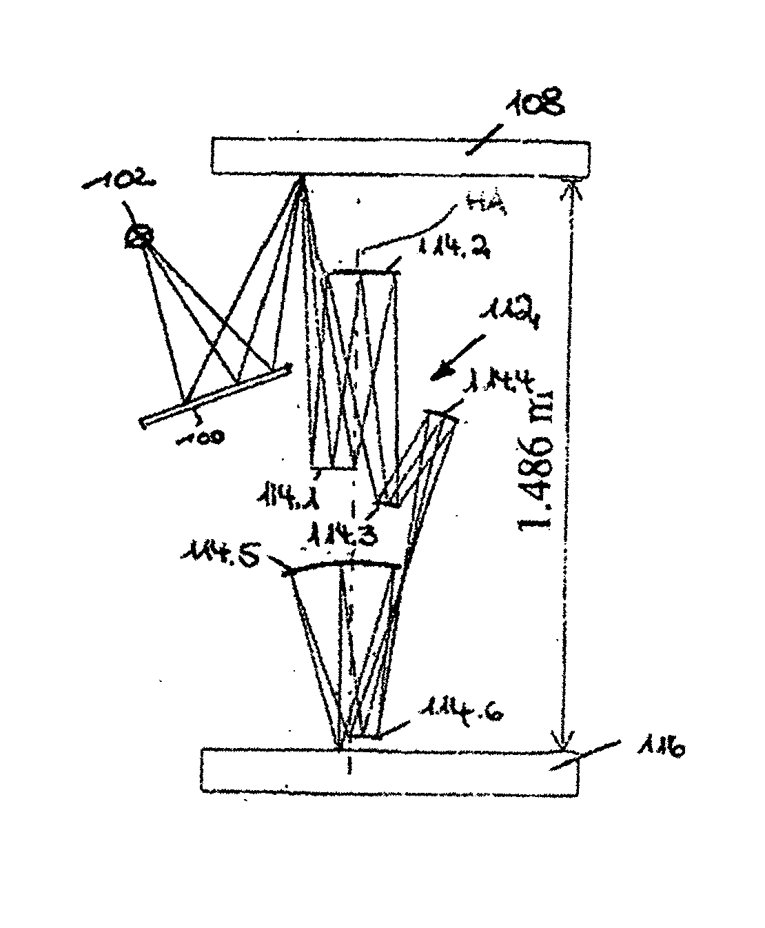
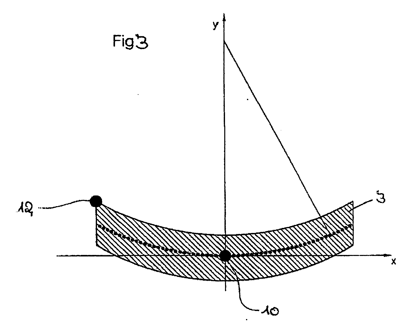
[0068] With the optical element according to the invention, a bundle focussed in a field plane will be deflected in such a way that an annular field segment will be formed in the field plane, and also—considered from a specific field point, for example, of an annular field segment—a pupil is illuminated, for example, of an illumination system in a pre given form, e.g., an annular or quadrupolar form.

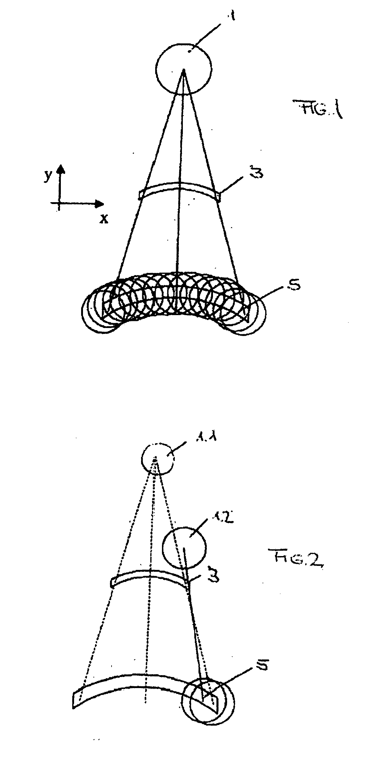
[0069] For this purpose, a specific amount of incident light is guided into the pupil of the illumination system which belongs to a field point of the field of an illumination system. This can be done, for example, by means of small planar facets. The planar facets are thus disposed in such a way that the field is illuminated homogeneously in the field plane and a homogeneously filled pupil is formed for each field point, i.e., the pupil is filled with discrete, but well, distributed “points”. This principle is shown in FIG. 1, which is also designated as the principle of the specular r...


PUM


Abstract

There is provided an optical element for an illumination system for wavelengths of ≦193 nm. The illumination sytem includes a light source, a field plane, an exit pupil, and a plurality of facets. The plurality of facets receives light from the light source and guides the light to a plurality of discrete points in the field plane. The plurality of discrete points collectively illuminate a field in the field plane, and each of the plurality of facets illuminates a region of the exit pupil.

Description

CROSS-REFERENCE TO RELATED APPLICATIONS [0001] The present application is a continuation of International application number PCT / EP2004 / 003855, filed Apr. 13, 2004, the content of which is herein incorporated by reference. BACKGROUND OF THE INVENTION [0002] 1. Field of the Invention [0003] The invention concerns an optical element for an illumination system with wavelengths of ≦193 nm, in particular for EUV lithography, wherein the illumination system comprises a light source, a field plane as well as an exit pupil and the illumination system has a plurality of facets. [0004] In a particularly preferred embodiment, the invention further provides an illumination system for wavelengths of ≦193 nm, in particular for EUV lithography, which is characterized in that the optical element has a plurality of facets, wherein the facets on the optical element have an arrangement such that a field in the field plane as well as the exit pupil are illuminated in a predetermined shape with this opt...

Claims


Application Information

Patent Timeline
IPC IPC(8): G03B27/54G03F7/20
CPCG03F7/70066G03F7/70108
Inventor SINGER, WOLFGANGANTONI, MARTIN
Owner CARL ZEISS SMT GMBH
Why Eureka
Try Eureka