Monitoring function-equipped dispensing system and method of monitoring dispensing device

a technology of function-equipped dispensing system and monitoring device, which is applied in the direction of analytical using chemical indicators, instruments, laboratory glassware, etc., can solve the problems of complex structure of optical measuring device, inability to perform optical measurement of the inside of the container from the outside, and inability to always be transparent in the container

Inactive Publication Date: 2006-06-22
UNIVERSAL BIO RESEARCH CO LTD
View PDF2 Cites 132 Cited by
  • Summary
  • Abstract
  • Description
  • Claims
  • Application Information

AI Technical Summary

Benefits of technology

[0076] The twentieth aspect of the present invention has a similar effect to that described for the twelfth aspect of the present invention.

Problems solved by technology

However, the container is not always transparent.
Moreover in the case of a container in which a large number of liquid storage portions are disposed, optical measurement of the inside of the container can not be performed from the outside of the container.
Therefore, there has been a problem in that the structure of the optical measuring device may become complicated, or the scale of the device may be enlarged.
Furthermore, even if the optical conditions in the pipelines that are inserted into the container can be measured from the side, there has been a problem in that determination of the sucking time only from the optical conditions is not always easy.
Moreover, by only performing optical measurement, it is difficult to detect clogging in the pipelines caused by solid bodies, viscous substances and the like contained in the liquid, with respect to the preset sucking and discharging time determined from the instructed liquid amount.
Moreover, a huge memory capacity is required to perform optical measurement at all times during the operation (for example, to obtain a dynamic image), and the analysis is also difficult.
Therefore, as the number of the pipelines is increased, the number of optical measuring devices is also increased, causing concern of enlarging the scale of the device.
Moreover, since the optical device is provided part way along the route where the pipelines are elevated / lowered, the presence of the optical device interferes with the operation or the observation of the pipelines by a user, thus making handling difficult.
Furthermore, due to the depth of the optical device in the optical axis direction, particularly in order to receive light from an area having a large angle for a visual field of a plurality of pipelines, it is necessary to extend the distance between the optical device and the pipelines, thus causing a problem in that the scale of the device may be enlarged, or the work area may be narrowed.
On the other hand, in a device provided with a pressure measuring device only, there has been a problem in that, even though the liquid surface can be detected, it is not possible to know whether or not sucking and discharging has been performed for an accurate liquid amount, nor conditions such as the hue of the liquid after completing the respective operations.
Moreover, in the case where a large number of containers are handled, there has been a problem in that, even if an inconvenience in the process of one container is found, operations for removing the inconvenience by stopping or repeating the process interfere with the other large number of normal processes.
Furthermore, there has been a problem in that, if the occurrence of such an inconvenience is previously assumed and a complicated control system having a feedback function is provided, the processing procedure may become complicated, the scale of the device may be enlarged, or the manufacturing cost of the device may be greatly increased.

Method used


Image

  • Monitoring function-equipped dispensing system and method of monitoring dispensing device
  • Monitoring function-equipped dispensing system and method of monitoring dispensing device
  • Monitoring function-equipped dispensing system and method of monitoring dispensing device

Examples


Embodiment Construction

[0086] Here is a description of a monitoring function-equipped dispensing system and a method of monitoring the dispensing system according to embodiments of the present invention, with reference to drawings. The description of the present embodiments should not be considered as limiting the present invention unless particularly specified.

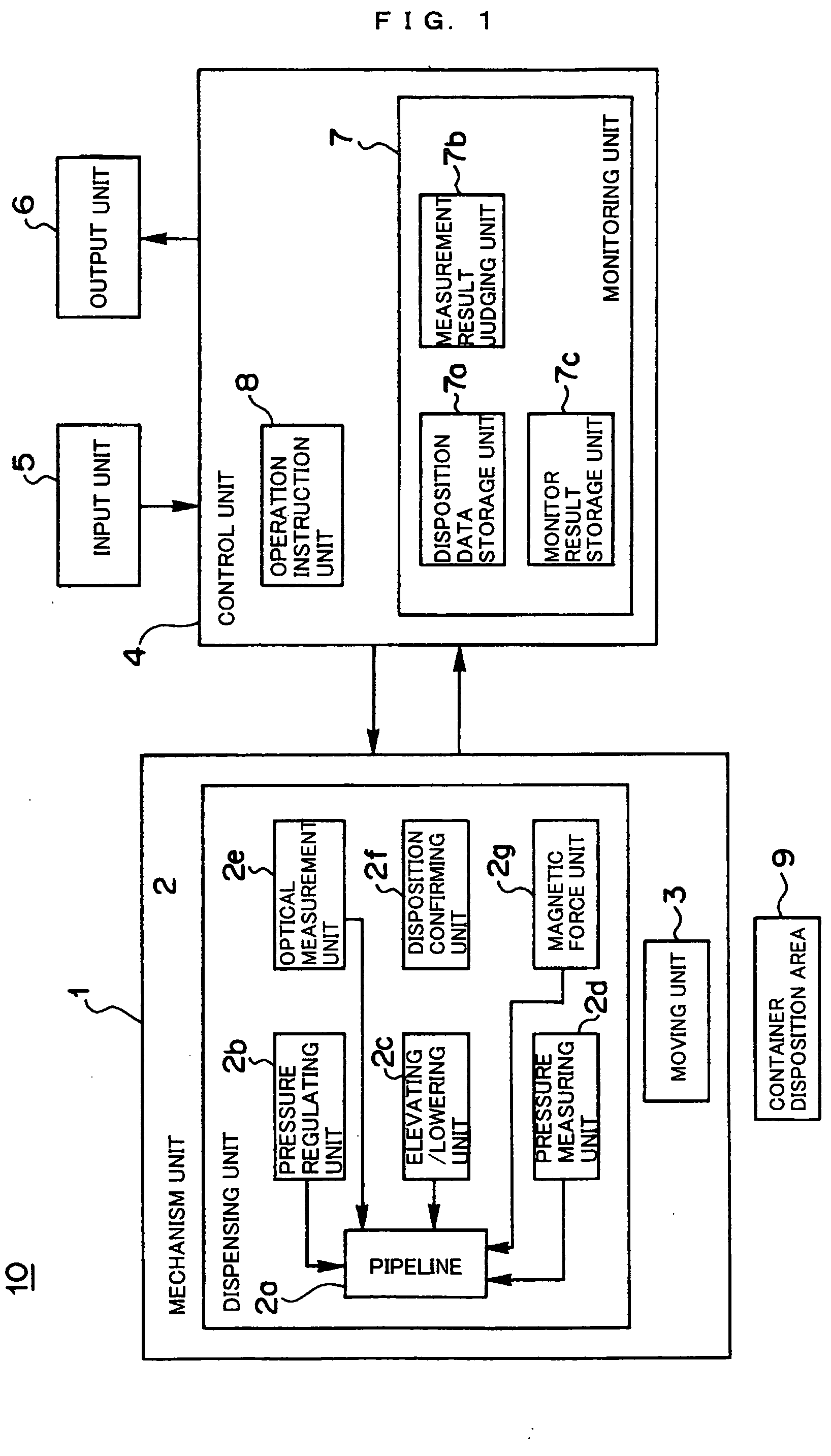
[0087]FIG. 1 is a block diagram of a monitoring function-equipped dispensing system 10 according to the embodiment of the present invention.

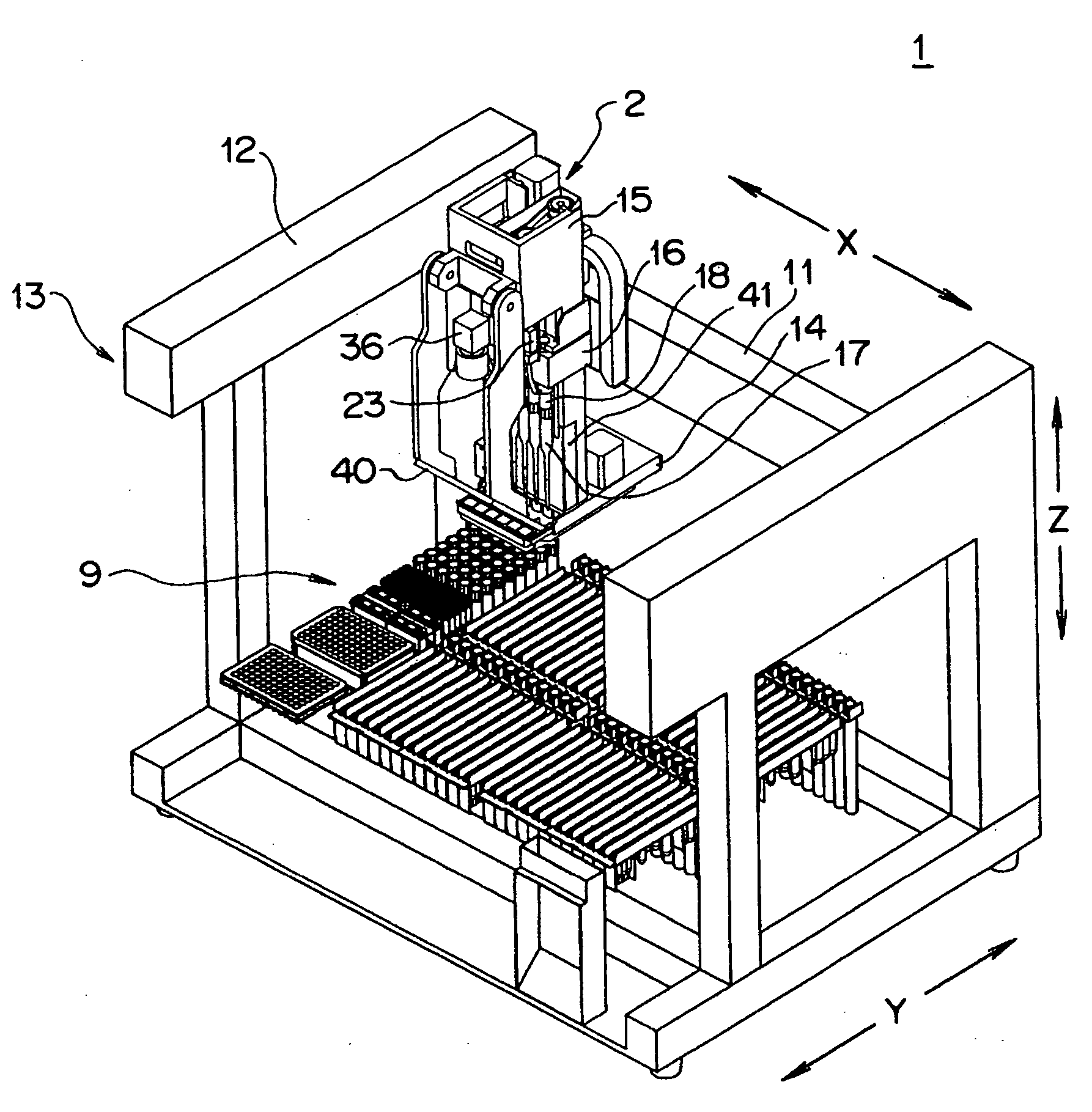
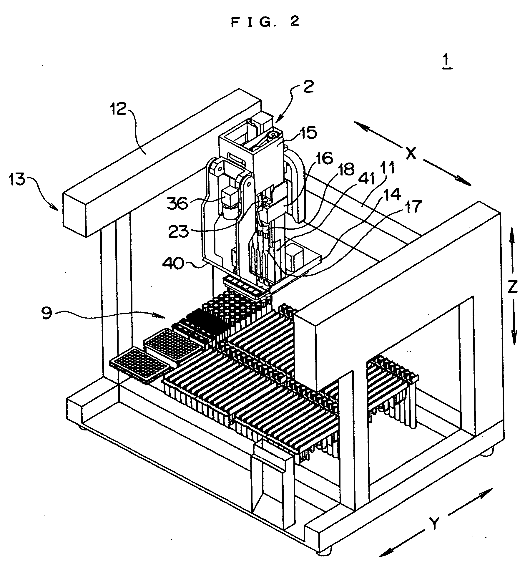
[0088] The monitoring function-equipped dispensing system 10 according to the present embodiment comprises: a mechanism unit 1 comprising a dispensing unit 2 which sucks and discharges a liquid with respect to a container, and a moving unit 3 which moves the dispensing unit 2 relatively with respect to a container; a control unit 4 which controls operation instructions and monitoring of the respective operations with respect to the mechanism unit 1 according to instructions from the outside; an input unit 5 w...


PUM

PropertyMeasurementUnit
sizeaaaaaaaaaa
sizeaaaaaaaaaa
translucentaaaaaaaaaa

Abstract

A monitoring function-equipped dispensing system and a method of monitoring the dispensing system wherein conditions in a pipeline can be identified accurately and precisely by not only optically measuring conditions in the pipeline, but performing other measurements reinforcing the former. The system comprises: one or more translucent or semi-translucent pipelines; one or more pressure regulating units which respectively regulate the pressures in the pipelines; an elevating/lowering unit which enables the pipelines to be elevated/lowered; a pressure measuring unit which measures the pressures in the respective pipelines when operation instructions are given to the pressure regulating unit; an optical measurement unit which optically measures the conditions of the pipelines above the container disposition area, when operations based on operation instructions including operation instructions to the pressure regulating unit are completed; and a monitoring unit which judges the conditions in the pipelines based on the operation instructions and measurement results of the pressure measuring unit and the optical measurement unit so as to obtain monitoring results that associate the judged results with respective pipelines and the operation instructions.

Description

TECHNICAL FIELD [0001] The present invention relates to a monitoring function-equipped dispensing system and a method of monitoring the dispensing system. More precisely, the invention relates to a monitoring function-equipped dispensing system comprising translucent or semi-translucent pipelines, pressure regulating units which respectively regulate the pressures in the pipelines to suck and discharge fluids with respect to the pipelines, and an elevating / lowering unit which enable the pipelines to be elevated / lowered, and to a method of monitoring the dispensing system. The system is useful in fields where highly accurate examination, operation, or processing having high quantitativity is required, in particular, such fields as chemistry including biochemistry, and medicine, pharmacology, engineering, agriculture, livestock industry, fisheries or the like. BACKGROUND ART [0002] Conventionally, there has been a device invented by the inventors of the present application for measuri...

Claims


Application Information

Patent Timeline
Patent Type & Authority Applications(United States)
IPC IPC(8): G01N35/00B01L3/00G01N35/10
CPCG01N35/1009G01N35/10
Inventor TAJIMA, HIDEJIHIRAHARA, YOSHINAO
Owner UNIVERSAL BIO RESEARCH CO LTD
Why Eureka
Try Eureka