Linear moving capacitive sensor twin column electronic height gauge

a capacitive sensor and electronic technology, applied in the field of gauges, can solve the problems of affecting the accuracy of the reading, creating improper readings and errors, and traditional electronic twin column height gauges, and achieve the effect of lowering measurement accuracy and high cos

Inactive Publication Date: 2006-06-29
INT PRECISION INSTR CORP
View PDF15 Cites 23 Cited by
  • Summary
  • Abstract
  • Description
  • Claims
  • Application Information

AI Technical Summary

Benefits of technology

[0009] In summary, the setbacks of the existing electronic twin column height gauges have resulted in higher costs, and lower measurement accuracy.

Problems solved by technology

In the situations when dirt and debris accumulate on the surface of the rack or the gear, or after periods of long term wear, the accuracy of the readings will be affected.
The traditional rack and gear systems working with a complicated data transferring system also may create improper readings and errors.
In summary the traditional electronic twin column height gauges have problems including that of a complicated structure, complicated assembly, high maintenance, high costs, and lower measurement accuracy.
In summary, the setbacks of the existing electronic twin column height gauges have resulted in higher costs, and lower measurement accuracy.

Method used


Image

  • Linear moving capacitive sensor twin column electronic height gauge
  • Linear moving capacitive sensor twin column electronic height gauge
  • Linear moving capacitive sensor twin column electronic height gauge

Examples


Embodiment Construction

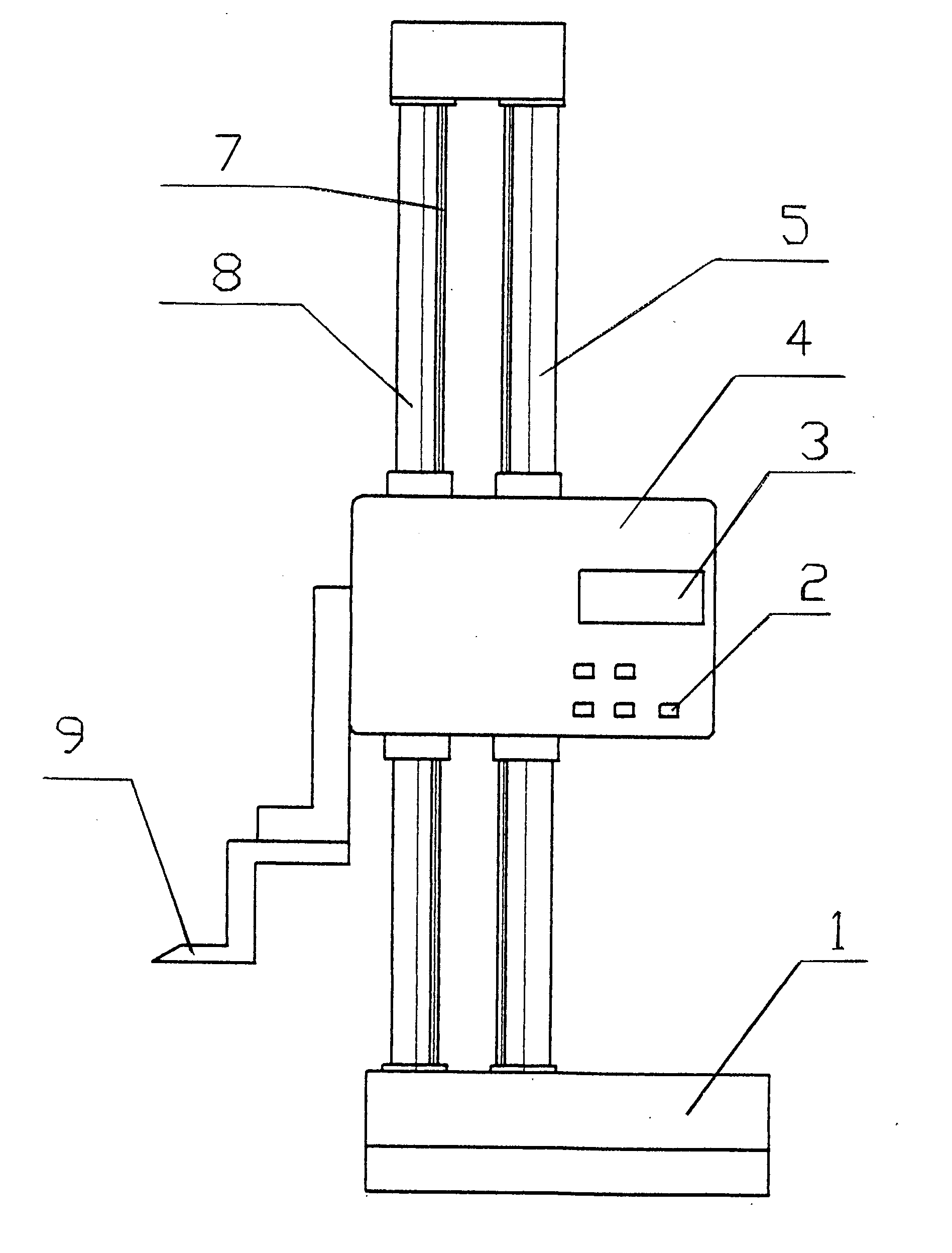
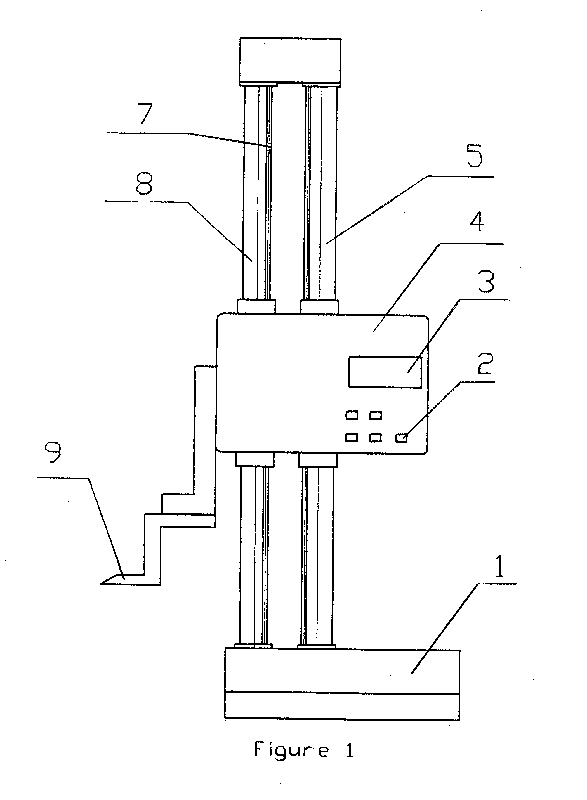
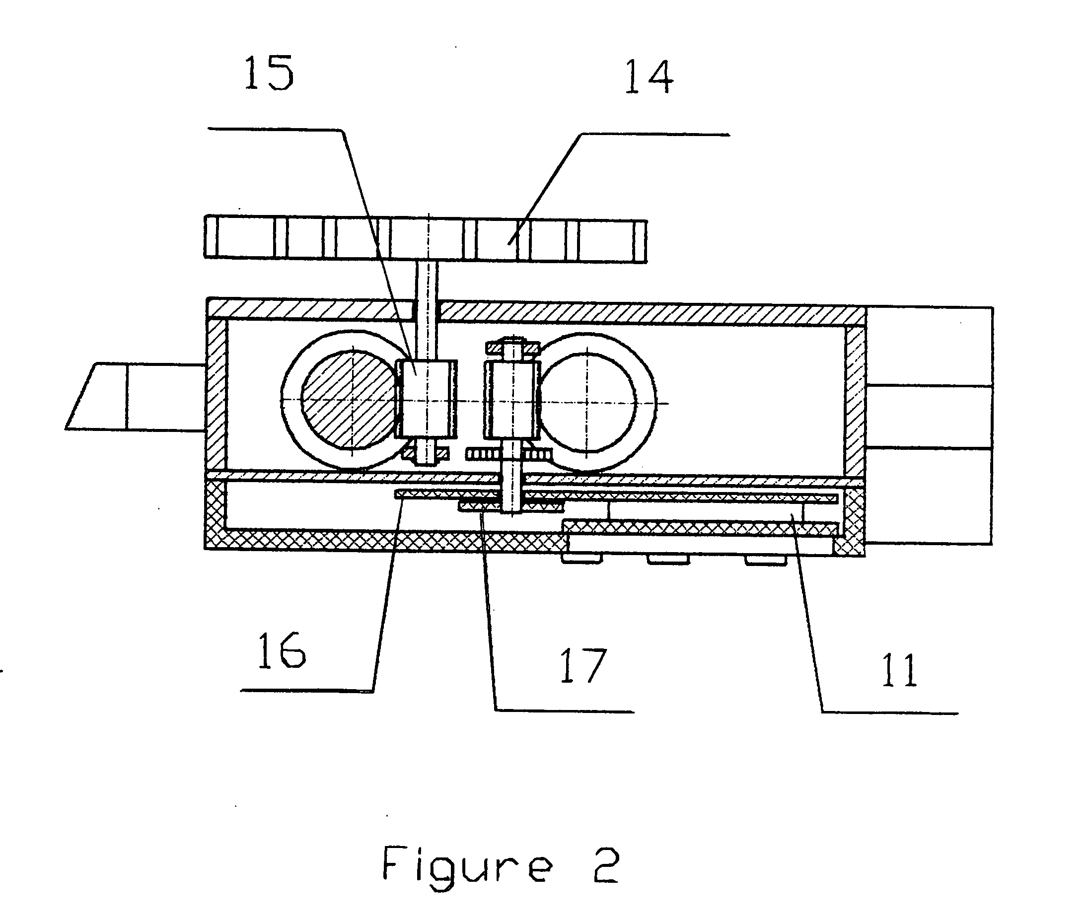
[0033] Detailed descriptions of the preferred embodiment are provided herein. It is to be understood, however, that the present invention may be embodied in various forms. Therefore, specific details disclosed herein are not to be interpreted as limiting, but rather as a basis for the claims and as a representative basis for teaching one skilled in the art to employ the present invention in virtually any appropriately detailed system, structure or manner. Referring to the drawing figures, like reference numerals designate identical or corresponding elements throughout the several figures, there is disclosed: (1) Base; (2) Buttons; (3) LCD Display; (4) display unit with cover; (5) Column 1; (6) fixed capacitance sensor; (7) toothed rack; (8) Column 2; (9) measuring scriber; (10) gear; (11) cable; (12) main electronic processor; (13) linear moving capacitance sensor; (14) handwheel.

[0034] The above features differ from those that exist on the market today: (15) gear system (existing ...


PUM


Abstract

The present invention is an electronic height gauge utilizing new technology and includes a first column (Column 1) and a second column (Column 2), a display unit with a cover, a measuring scriber, a fixed capacitance sensor and a linear moving capacitance sensor. The fixed capacitance sensor is located on a flat surface on Column 1, flat surface having a length equivalent to the length of Column 1. The linear moving capacitance sensor is located inside the display unit cover positioned to face the fixed capacitance sensor. The fixed capacitive sensor and linear moving capacitive sensors are facing toward each other only, and do not make direct physical contact with the fixed capacitor sensor when the height gauge is operating in upward and downward movements. The fixed and moving capacitive sensors are instead making only electrical contact with each other when the height gauge is making upward and downward movements. This linear direct data non-contact sensor transfer system results in high accuracy of measurements, which also ensures the repeatability of accurate measurements. Also, since the fixed capacitance sensor and the linear moving capacitance sensor have no physical contact with each other, there is no wear and tear damage on either component part, thereby leading to a longer life of use with stability in accurate measurements and repeatability. Because the measuring system is comparatively simple, and easy to assemble and service and maintain compared to the existing rotary capacitive sensor electronic height gauges that exist on the market, the overall cost of production and maintenance is minimized. On the second column (Column 2), a simple rack and gear system is added. These gears of column 2 are connected to a hand wheel located on the rear of the display unit. The handwheel is used for making upward and downward vertical movements. This rack and gear system of column 2 of the present invention is only used to aid the same in making upward and downward movements, and does not affect the measuring accuracy of the height gauge, as it did in the height gauges that have existed on the market.

Description

[0001] PRIORITY DATE OF DEC. 27, 2004 [0002] This application is submitted under and claims a priority date of Dec. 27, 2004 to a Chinese Patent Application with associated Patent Number 200420120573.x with filing date of Dec. 27, 2004 and claims priority thereto. BACKGROUND OF THE INVENTION [0003] 1. Field of the Invention [0004] The present invention relates to the field of gauges and specifically to an electronic twin column height gauge using new technology offering high accuracy of measurements. [0005] 2. Brief Description of the Related Art [0006] The measuring technology as applied to electronic twin column height gauges as they currently exist on the market today use a rotary senor system of racks and gears. Racks are usually flat toothed racks (usually located on twin beams) and are geared up with a gear (usually located inside the display unit) thereby creating vertical up and down movements. [0007] The electronic twin column height gauges on the market today utilize a rot...

Claims


Application Information

Patent Timeline
Patent Type & Authority Applications(United States)
IPC IPC(8): G01B3/22
CPCG01B7/082
Inventor YANG, ZHONG YI
Owner INT PRECISION INSTR CORP
Why Eureka
Try Eureka