
Method and system for manufacturing a package

Inactive Publication Date: 2006-06-29
AJINIHON
View PDF12 Cites 68 Cited by
  • Summary
  • Abstract
  • Description
  • Claims
  • Application Information

AI Technical Summary

Benefits of technology

[0019] This method and system make it possible to manufacture easy-to-open packages each having plural elongate scars formed to extend adjacent and substantially perpendicularly to a side edge in a side edge portion thereof with use of a scar-free film. Hence, the method and system can reduce the cost of manufacturing such easy-to-open packages and shorten the lead time for the manufacture of the easy-to-open packages. Further, since each package is not yet turned into an easy-to-open package at the time of package sealing, a displacement of the film can be corrected by applying a tensile force to the film. Therefore, it becomes easy to adjust the position of the film during the manufacture of the packages in order to prevent a printed mark on the surface of each package from being displaced.
[0021] Such a feature enables the above-described invention to be carried out easily and reliably. Further, since this feature allows the number of stacked disks to increase or decrease in accordance with a processing precision with which the package-joining belt is to be processed, unnecessary cutting edges can be eliminated.
[0023] This feature allows packages to be subjected to predetermined processing and, hence, can improve the function of the system for manufacturing a package.
[0024] The method and system for manufacturing a package according to the present invention make it possible to manufacture easy-to-open packages each having plural elongate scars formed to extend adjacent and substantially perpendicularly to the side edge in the side edge portion with use of a scar-free film and hence enjoy the advantages in reducing the cost of manufacturing such easy-to-open packages, shortening the lead time for the manufacture of the easy-to-open packages, relaxing the restricting conditions imposed on the packaging operation due to the film having poor tensile strength, and facilitating positional adjustment of a printed surface of the film during the manufacture of the easy-to-open packages.

Problems solved by technology

In addition, scarred films each suited to a respective one of packages to be manufactured need be prepared troublesomely.
Further, the provision of scars causes the tensile strength of the film to lower, which is one of packaging operation restricting factors.
With a packaging machine configured to draw a film with a large tensile force, such as a high-speed packaging machine for example, a trouble occasionally occurs such that a film formed with scars tears during the packaging operation, which lowers the operating efficiency considerably.
In such a case, a film formed with scars has insufficient tensile strength for such adjustment, which makes the adjustment very difficult actually.
Although, presently, such easy-to-open packages are manufactured using scarred films solely, there has not so far been known any radical means to solve the foregoing problems essential to such scarred films as a result of study made by those skilled in the art but some studies to improve only the characteristics of film itself.

Method used


Image

  • Method and system for manufacturing a package
  • Method and system for manufacturing a package
  • Method and system for manufacturing a package

Examples


embodiment 1

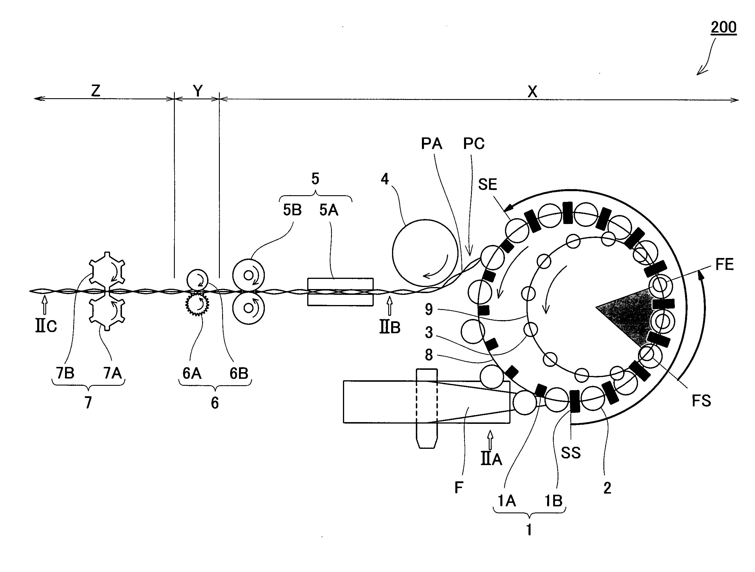
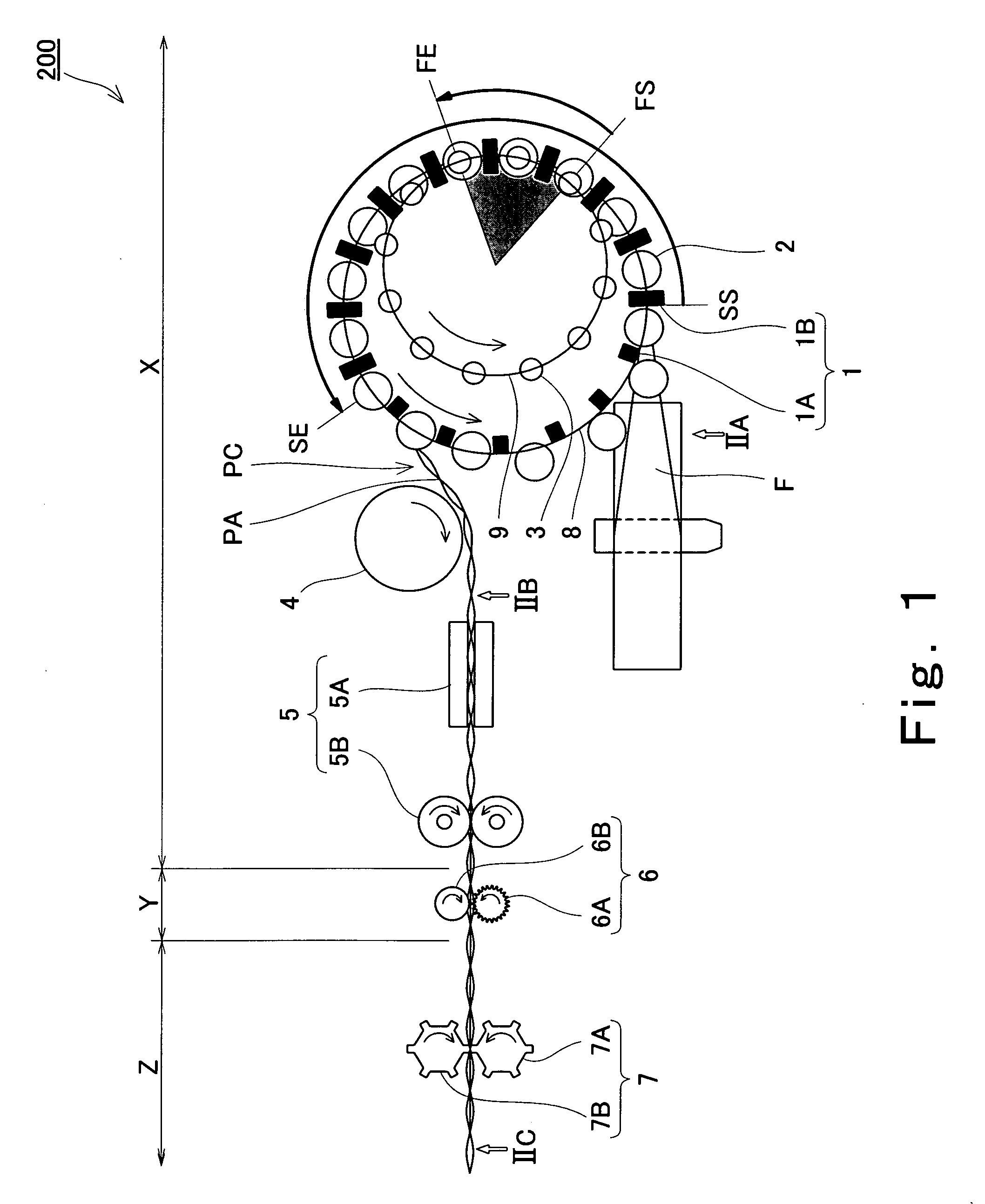
[0034] Initially, description will be made of the construction of a package manufacturing system (a system for manufacturing a package) 200 according to this embodiment.

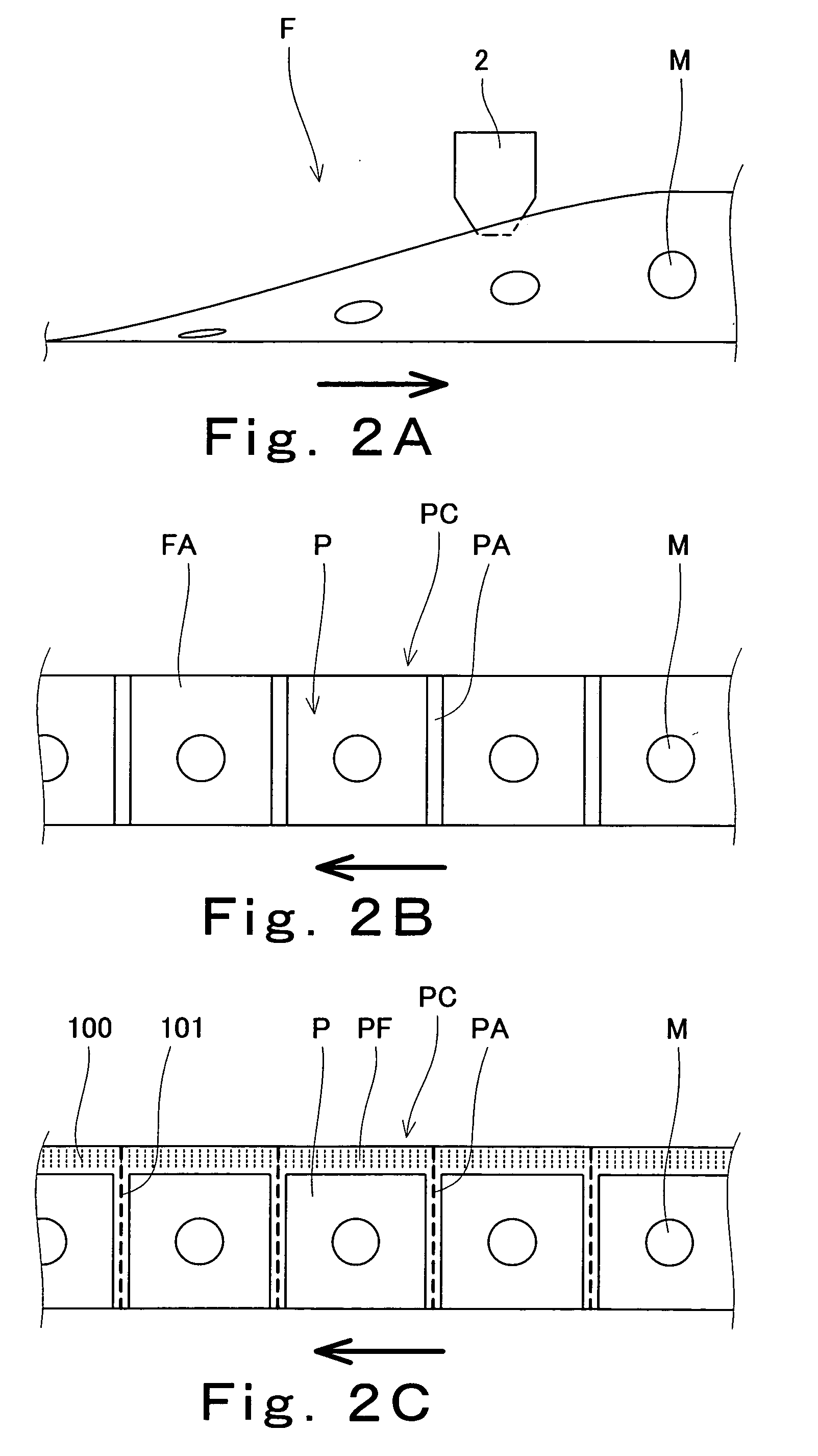
[0035]FIG. 1 is a top plan view schematically showing an example of the construction of the package manufacturing system according to embodiment 1 of the present invention; and FIGS. 2A, 2B and 2C are each a view as viewed in a respective one of the directions indicated by arrows IIA, IIB and IIC of FIG. 1.

[0036] Referring to FIG. 1, the package manufacturing system 200 includes a package-joining belt forming unit X, a scar forming unit Y, and a package processing unit (perforating unit) Z. These units are disposed so that a package-joining belt PC formed from a belt-shaped film F or a film F passes through the package-joining belt forming unit X, scar forming unit Y and package processing unit Z in this order. The package-joining belt forming unit X includes inner peripheral seal bars 1A, outer peripheral seal bar...

embodiment 2

[0066] Embodiment 2 includes a package-joining belt forming unit X which is advantageously used when the filling material is a liquid. Since the structure and operation of scar forming unit Y used in this embodiment are the same as in embodiment 1, description thereof will be omitted.

[0067]FIG. 5 is a perspective view schematically showing an example of the construction of a package manufacturing system according to embodiment 2 of the present invention. Like reference characters are used to designate like or corresponding parts throughout FIGS. 1 and 5 to eliminate description thereof.

[0068] The package manufacturing system 210 shown includes package-joining belt forming unit X, scar forming unit Y, and package processing unit (cutting unit) Z, the units X, Y and Z being arranged vertically as a whole. These units are disposed so that package-joining belt PC formed from a belt-shaped film F or a film F passes through the package-joining belt forming unit X, scar forming unit Y an...

embodiment 3

[0087] Embodiment 3 is an embodiment wherein package processing unit Z is a folding unit configured to fold package-joining belt PC. Since the package manufacturing system according to this embodiment is similar to the foregoing package manufacturing system 200 or 210 in the structure and operation of each of package-joining belt forming unit X, scarring device 6 and feed roller 9, description of the structures and operations of these components will be omitted and description will be made of the structure and operation of each of scar forming unit Y and package processing unit Z.

[0088]FIG. 6 is a perspective view schematically showing an arrangement of a scar forming unit and a package processing unit in the package manufacturing system according to embodiment 3 of the present invention. Like reference characters are used to designate like or corresponding parts throughout FIGS. 1, 2A, 2B, 2C, and 6 to eliminate description thereof. In FIG. 6 the package-joining belt forming unit ...


PUM

PropertyMeasurementUnit
Lengthaaaaaaaaaa
Thicknessaaaaaaaaaa

Abstract

A method and system for manufacturing a package include: a package-joining belt forming step for forming a package-joining belt (PC) in which packages (P) each containing a material filled in between superposed films and each sealed by joint portions (PA) and a side edge portion (PF) are joined with each other by the joint portions (PA), the package-joining belt forming step including: a superposing process of forming superposed films; a joint portion forming process of forming band-shaped joint portions (PA); a side edge portion forming process of forming band-shaped side edge portion (PF); and a filling process of filling the material; and a scar forming step for forming plural elongate scars (100) each extending adjacent and substantially perpendicularly to the side edge in the side edge portion (PF), wherein the package-joining belt forming step and the scar forming step are carried out, while the package-joining belt is drawn.

Description

BACKGROUND OF THE INVENTION [0001] 1. Field of the Invention [0002] The present invention relates to a method and system for manufacturing a package. More particularly, the invention relates to a method and system for manufacturing a package each having a band-like side edge portion formed by joining films together. [0003] 2. Description of the Related Art [0004] A package of the type shaped like a pouch by superposing films one upon another and then joining their respective edge portions together (hereinafter will be referred to as package) has been widely used as a package for containing a filling material comprising ingredients of an instant food, or powder or liquid such as a seasoning. [0005] In general, a packaging machine is configured to manufacture such packages as follows. Initially, one belt-shaped film is folded widthwise to have superposed film portions, or two belt-shaped films are superposed upon each other (superposing process). [0006] Subsequently, the superposed fi...

Claims


Application Information

Patent Timeline
IPC IPC(8): B65B9/06
CPCB29C65/7885B29C66/0242B29C66/032B29C66/0326B29C66/1122B29C66/3452B29C66/4312B29C66/4322B29C66/83413B29C66/83511B29C66/83513B29C66/83543B29C66/849B29C2793/0045B29C2793/009B65B9/087B65B9/2021B65B9/207B65B51/306B65B61/007B65B61/18B65B2220/10B65B2220/18B65B2220/22B29C66/72321B29C66/72343
Inventor OSHITA, KAZUMICHISHINBUTSU, KENJITOMINAGA, YOICHI
Owner AJINIHON
Learn More