Container structure for removal of vacuum pressure

a container and vacuum technology, applied in the field of container structures, can solve the problems of vacuum pressure, reduced volume of liquid in the container, vacuum pressure, etc., and achieve the effects of greater vacuum pressure removal, greater inward and longitudinal movement, and greater resistance to outward deflection

Inactive Publication Date: 2006-06-29
CO2 PAC
View PDF99 Cites 149 Cited by
  • Summary
  • Abstract
  • Description
  • Claims
  • Application Information

AI Technical Summary

Benefits of technology

[0025] It is a further object of one preferred embodiment of the present invention to provide a container which has a transversely oriented pressure panel that is decoupled to a degree from the adjoining wall such that greater inward and longitudinal movement can be achieved.
[0035] Preferably in one embodiment the vacuum panel portion may include fluting structures or the like to allow an even circumferential distribution of folding forces to provide for increased control over folding the panel portion from one inclined position to another and to assist in preventing unwanted return to the original position.

Problems solved by technology

Once the liquid cools down in a capped container, however, the volume of the liquid in the container reduces, creating a vacuum within the container.
This liquid shrinkage results in vacuum pressures that pull inwardly on the side and end walls of the container.
This in turn leads to deformation in the walls of plastic bottles if they are not constructed rigidly enough to resist such force.
All such prior art, however, provides for flat or inwardly inclined, or recessed base surfaces.
Unfortunately, however, the force generated under vacuum to pull longitudinally on the base region is only half that force generated in the transverse direction at the same time.
Therefore, adequate vacuum compensation can only be achieved by placing vertically-oriented vacuum panels over a substantial portion of the circumferential wall area of a container, typically 60% of the available area.
Even with such substantial displacement of vertically-oriented panels, however, the container requires further strengthening to prevent distortion under the vacuum force.
The liquid shrinkage derived from liquid cooling, causes a build up of vacuum pressure.
The more difficult the structure is to defied inwardly, the more vacuum force will be generated.
In prior art, a substantial amount of vacuum is still present in the container and this tends to distort the overall shape unless a large, annular strengthening ring is provided in horizontal, or transverse, orientation at least a ⅓ of the distance from an end to the container.
Further, even if the base region could provide for enough flexure to accommodate all liquid shrinkage within the container, there would be a significant vacuum force present, and significant stress on the base standing ring.
For this reason it has not been possible to provide container designs in plastic that do not have typical prior art vacuum panels that are vertically oriented on the sidewall.
Many manufacturers have therefore been unable to commercialize plastic designs that are the same as their glass bottle designs with smooth sidewalls.
However, the technique disclosed, and the stated percentage areas required for efficiency are not considered by the present applicant to provide a viable solution to the problem.
In fact, flexure in the base region is recognised to be greatest in a horizontally flat base region, and maximizing such flat portions on the base has been well practiced and found to be unable to provide enough vacuum compensation to avoid also employing vertically oriented vacuum panels.
Whilst this may strengthen the region in order to allow more vacuum force to be applied to it, the ribs conversely further reduce flexibility within the base region, and therefore reduce flexibility.
It is believed by the present applicant that the specific ‘ribbed’ method proposed by Silvers could only provide for approximately 35% of the vacuum compensation that is required, as the modified end-wall is not considered capable of sufficient inward flexure to fully account for the liquid shrinkage that would occur.
Containers employing such base structure therefore still require significant thickening of the sidewalls, and as this is done the base region also becomes thicker during manufacturing.
The result is a less flexible base region, which in turn also reduces the efficiency of the vacuum compensation achieved.
A problem exists when locating such a panel in the end-wall or base region, whereby stability may be compromised if the panel does not move far enough into the container longitudinally to no longer form part of the container touching the surface the container stands on.
A further problem exists when utilizing a transverse panel in the base end-wall due to the potential for shock deflection of the inverted panel when a full and capped container is dropped.

Method used


Image

  • Container structure for removal of vacuum pressure
  • Container structure for removal of vacuum pressure
  • Container structure for removal of vacuum pressure

Examples


Embodiment Construction

[0064] The following description of preferred embodiments is merely exemplary in nature, and is in no way intended to limit the invention or its application or uses.

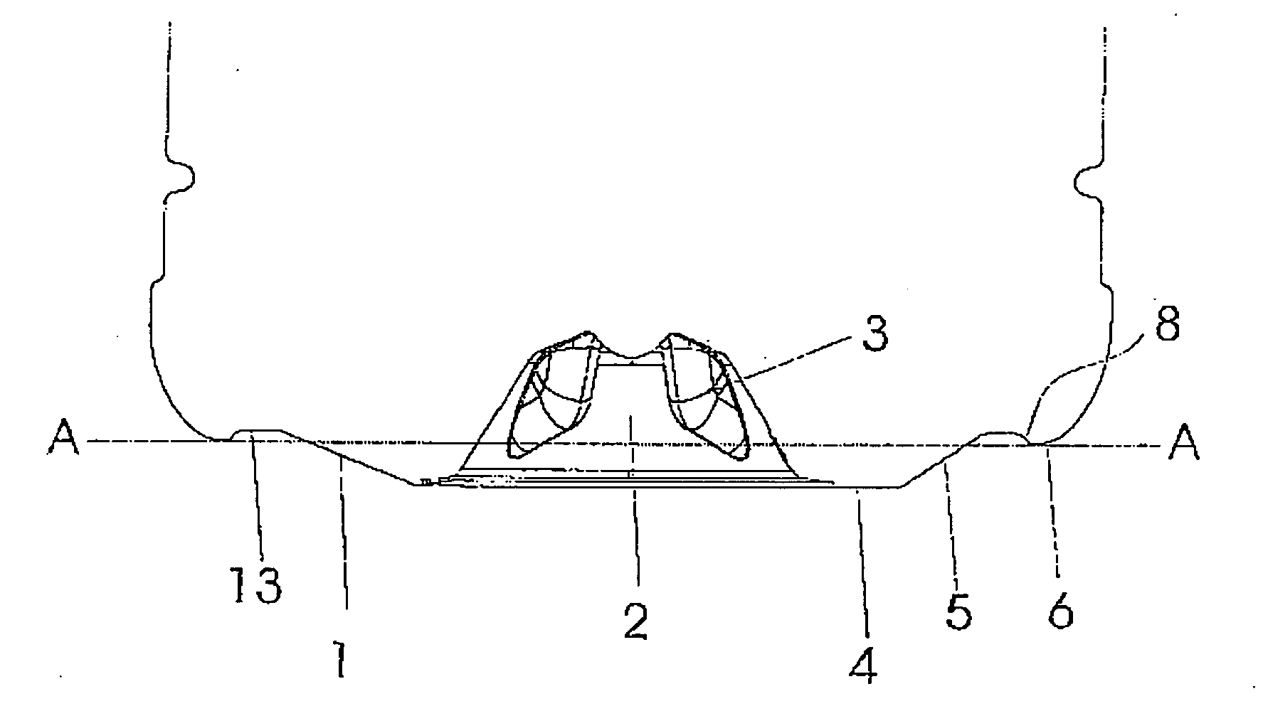
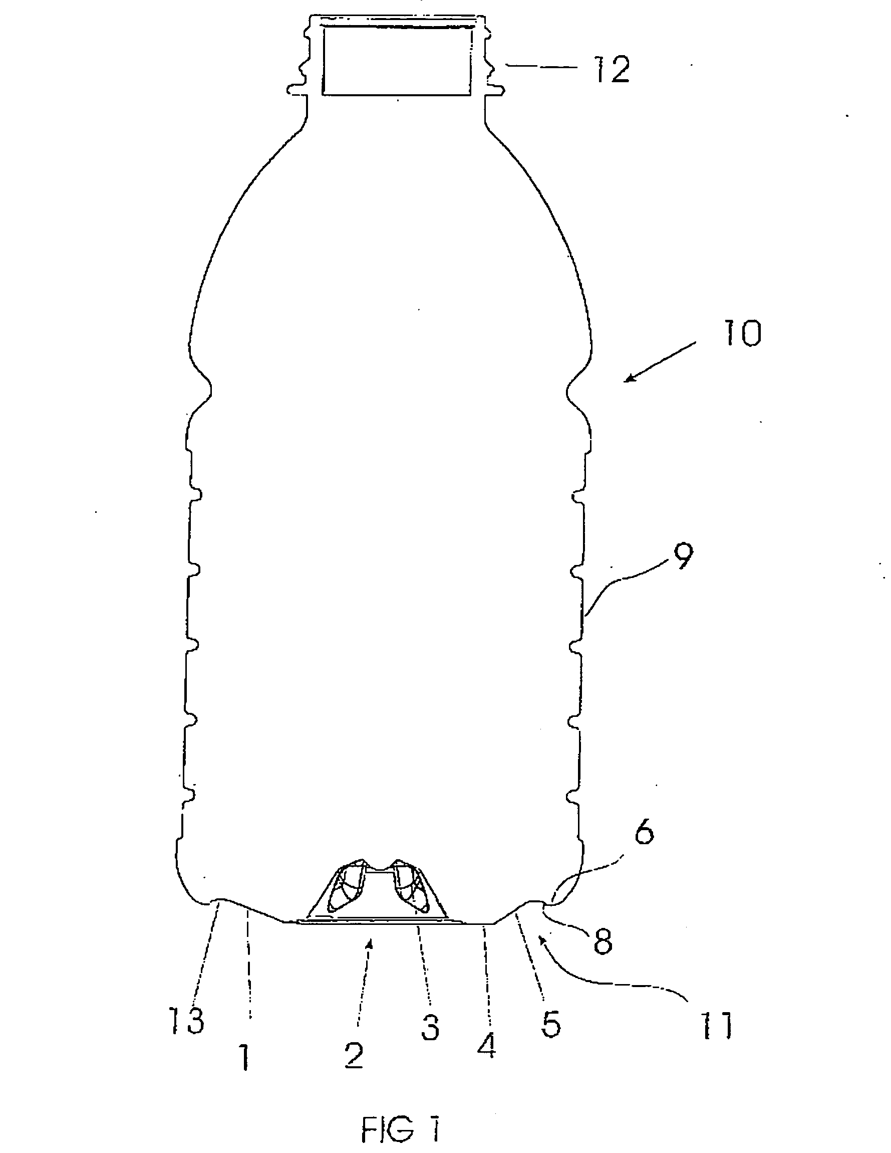
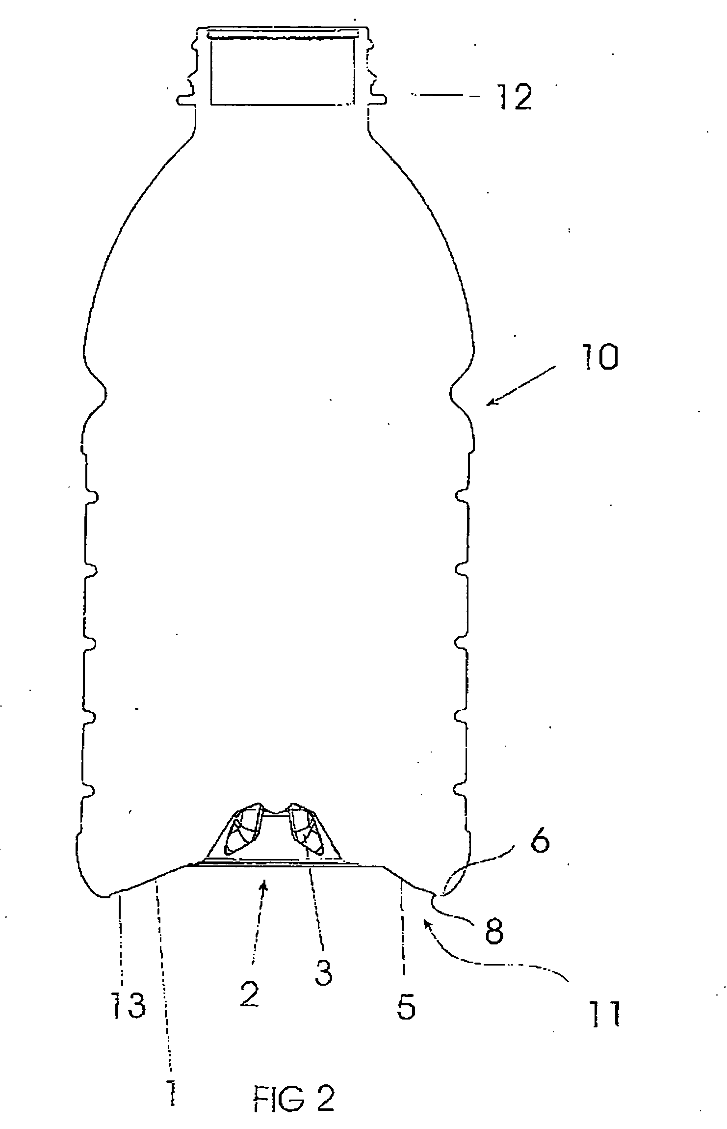
[0065] As discussed above, to accommodate vacuum forces during cooling of the contents within a heat set container, containers have typically been provided with a series of vacuum panels around their sidewalls and an optimized base portion. The vacuum panels deform inwardly, and the base deforms upwardly, under the influence of the vacuum forces. This prevents unwanted distortion elsewhere in the container. However, the container is still subjected to internal vacuum force. The panels and base merely provide a suitably resistant structure against that force. The more resistant the structure the more vacuum force will be present. Additionally, end users can feel the vacuum panels when holding the containers.

[0066] Typically at a bottling plant the containers will be filled with a hot liquid and then capped before being ...


PUM

PropertyMeasurementUnit
angleaaaaaaaaaa
angleaaaaaaaaaa
angleaaaaaaaaaa

Abstract

A hot-fill PET container or bottle (10) filling with a liquid at an elevated temperature has a side wall (9) extending to a lower portion including a pressure panel (11) and a base (21) in its unfolded or pre-fill position. The panel (11) is transversely oriented and has a decoupling or hinge structure (13), an initiator portion (1) and control portion (5) of a steeply angled inverting conical section between 30 and 45 degrees. The control portion enables the inversion of the panel (11) into the container (10) to compensate for vacuum or reduced pressure induced within the container as the liquid cools down. The base (2) can also have a plurality of reinforcing ribs (3).

Description

TECHNICAL FIELD OF THE INVENTION [0001] This invention relates generally to a container structure that allows for the removal of vacuum pressure. This is achieved by inverting a transversely oriented vacuum pressure panel located in the lower end-wall, or base region of the container.BACKGROUND [0002] So called ‘hot fill’ containers are well known in prior art, whereby manufacturers supply PET containers for various liquids which are filled into the containers and the liquid product is at an elevated temperature, typically at or around 85 degrees C. (185 degrees F.). [0003] The container is manufactured to withstand the thermal shock of holding a heated liquid, resulting in a ‘heat-set’ plastic container. This thermal shock is a result of either introducing the liquid hot at filling, or heating the liquid after it is introduced into the container. [0004] Once the liquid cools down in a capped container, however, the volume of the liquid in the container reduces, creating a vacuum wi...

Claims


Application Information

Patent Timeline
Patent Type & Authority Applications(United States)
IPC IPC(8): B65D90/02B65D6/28B65D1/02B65D1/14B65D79/00
CPCB65B61/24B65D1/0276B65D1/0261B65D79/00B65B3/04B65D79/005B67C2003/226B65D79/0081B29C49/4283B65D1/02B65D1/14
Inventor MELROSE, DAVID MURRAY
Owner CO2 PAC
Why Eureka
Try Eureka