Ventilation apparatus

Inactive Publication Date: 2006-06-29
SAMSUNG ELECTRONICS CO LTD
View PDF7 Cites 25 Cited by
  • Summary
  • Abstract
  • Description
  • Claims
  • Application Information

AI Technical Summary

Benefits of technology

[0010] The present general inventive concept provides a ventilation apparatus having a simplified v

Problems solved by technology

However, it has a problem in that a thermal efficiency is low relatively and a noise is high during rotating at high speed.
Also, the linear type ventilation apparatus has problems in that an energy efficiency is low, a structure is comple

Method used


Image

  • Ventilation apparatus
  • Ventilation apparatus
  • Ventilation apparatus

Examples


Embodiment Construction

[0025] Reference will now be made in detail to the embodiments of the present general inventive concept, examples of which are illustrated in the accompanying drawings, wherein like reference numerals refer to like elements throughout.

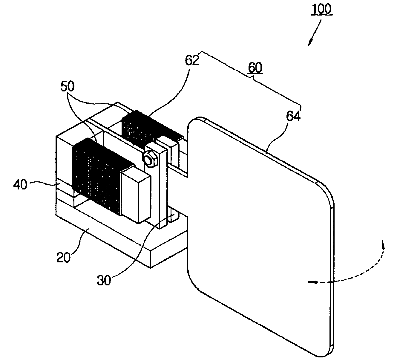
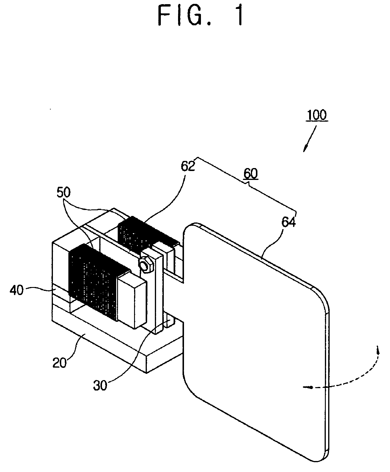
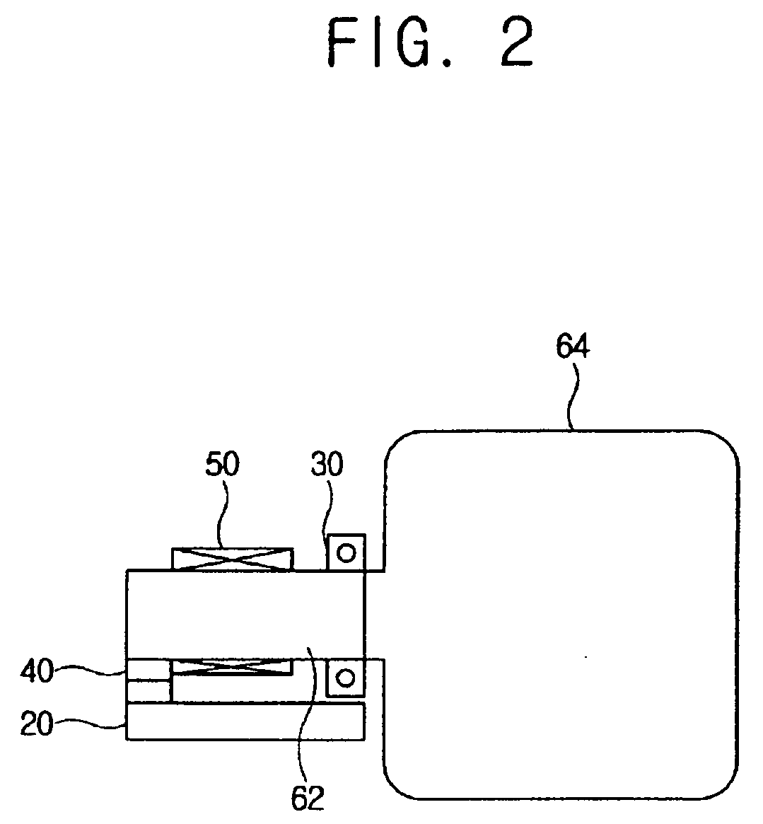
[0026] As shown in FIGS. 1 to 3, a ventilation apparatus 100 according to an embodiment of the present general inventive concept comprises a stator 20, a vibrator 30 arranged close to the stator 20, a permanent magnet 40 to generate a magnetic flux to form a path of the magnetic flux along the stator 20 and the vibrator 30, a coil 50 wound around the stator 20, and a ventilator 60 coupled to the vibrator 30.

[0027] When an electric current is applied to the coil 50, and the magnetic flux of the permanent magnet 40 is changed, the vibrator 30 generates a linear reciprocating motion according to the changes of the direction of the magnetic flux. The ventilator 60 is operated by the linear reciprocating motion of the vibrator 30. That is, the vibrator 30...


PUM


Abstract

A ventilation apparatus includes a stator, a vibrator arranged close to the stator, a permanent magnet to generate a magnet flux to form a path of the magnet flux along the stator and the vibrator, a coil wound around the stator or vibrator, and a ventilator coupled to the vibrator and operated by a linear reciprocating motion of the vibrator generated when an electric current is applied to the coil to change the magnet flux of the permanent magnet. Thus, the ventilation apparatus having a simplified ventilation structure increases a ventilation efficiency.

Description

CROSS-REFERENCE TO RELATED APPLICATIONS [0001] This application claims the benefit of Korean Patent Application No. 2004-112129, filed on Dec. 24, 2004, in the Korean Intellectual Property Office, the disclosure of which is incorporated herein by reference. BACKGROUND OF THE INVENTION [0002] 1. Field of the Invention [0003] The present general inventive concept relates to a ventilation apparatus, and more particularly, to a ventilation apparatus having an improved ventilation structure, and an electronic system having the same. [0004] 2. Description of the Related Art [0005] Generally, a ventilation apparatus is a device causing air to flow. The ventilation apparatus is classified into a rotary type ventilation apparatus, a linear type ventilation apparatus, and so on according to an operating character, and mainly used in an air conditioning system, an air induction / exhaustion system, or a cooling system. [0006] The rotary type ventilation apparatus includes a motor, such as a dome...

Claims


Application Information

Patent Timeline
IPC IPC(8): H02K35/00
CPCF04D33/00F04D25/08F04D29/263F04D29/002F05D2210/12F05D2260/404Y10S415/00Y10S417/00
Inventor KIM, SUNG KIKIM, SEO-YOUNGKIM, SEUNG-JONGKIM, WON-OYUN
Owner SAMSUNG ELECTRONICS CO LTD
Why Eureka
Try Eureka