
Motor for electric power steering and method for manufacturing the same

a technology of electric power steering and motors, which is applied in the direction of dynamo-electric machines, electrical apparatus, windings, etc., can solve the problems of increasing the size of the connecting portion, the limited mounting space of the motor, and the inability to install the motor, so as to achieve easy coil connection, small size, and easy coil connection

Inactive Publication Date: 2006-06-29
HITACHI LTD
View PDF10 Cites 124 Cited by
  • Summary
  • Abstract
  • Description
  • Claims
  • Application Information

AI Technical Summary

Benefits of technology

[0008] An object of the present invention is to provide a small-sized motor for electric power steering, in which coil connection can be easily performed with space saving, and a method for manufacturing the motor.
[0009] The motor for electric power steering according to the present invention has a small size and enables the coil connection to be easily performed with space saving.
[0012] According to the present invention, the size of a wiring connecting portion of the motor can be reduced and the connecting operation can be facilitated.

Problems solved by technology

In the first-mentioned known motor, however, the size of a connecting portion is increased and a larger space is required to accommodate the connecting portion.
Accordingly, in the case of a motor having a limitation in mount space, e.g., a small-sized motor for use in electric power steering, employment of the known connecting structure inevitably increases the motor size to such an extent that the motor cannot be installed in the limited mount space.
Also, when the flat-plate conductors are employed as disclosed in JP-A-2003-134724, an operation for joining the coils and the flat-plate conductors to each other is interfered with in areas where the flat-plate conductors are withdrawn out of the motor, thus resulting in deterioration of assembly efficiency.

Method used


Image

  • Motor for electric power steering and method for manufacturing the same
  • Motor for electric power steering and method for manufacturing the same
  • Motor for electric power steering and method for manufacturing the same

Examples


Embodiment Construction

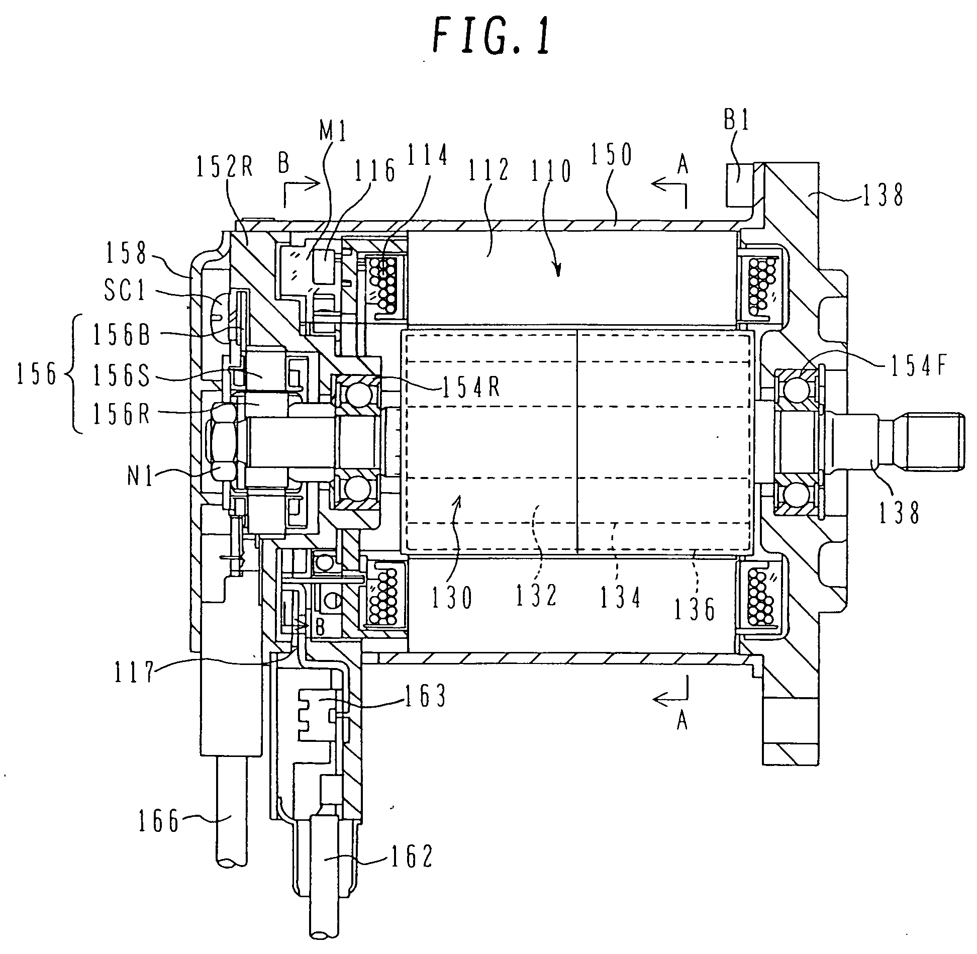
[0033] The structure and operation of a motor for electric power steering system according to one embodiment of the present invention will be described below with reference to FIGS. 1-16.

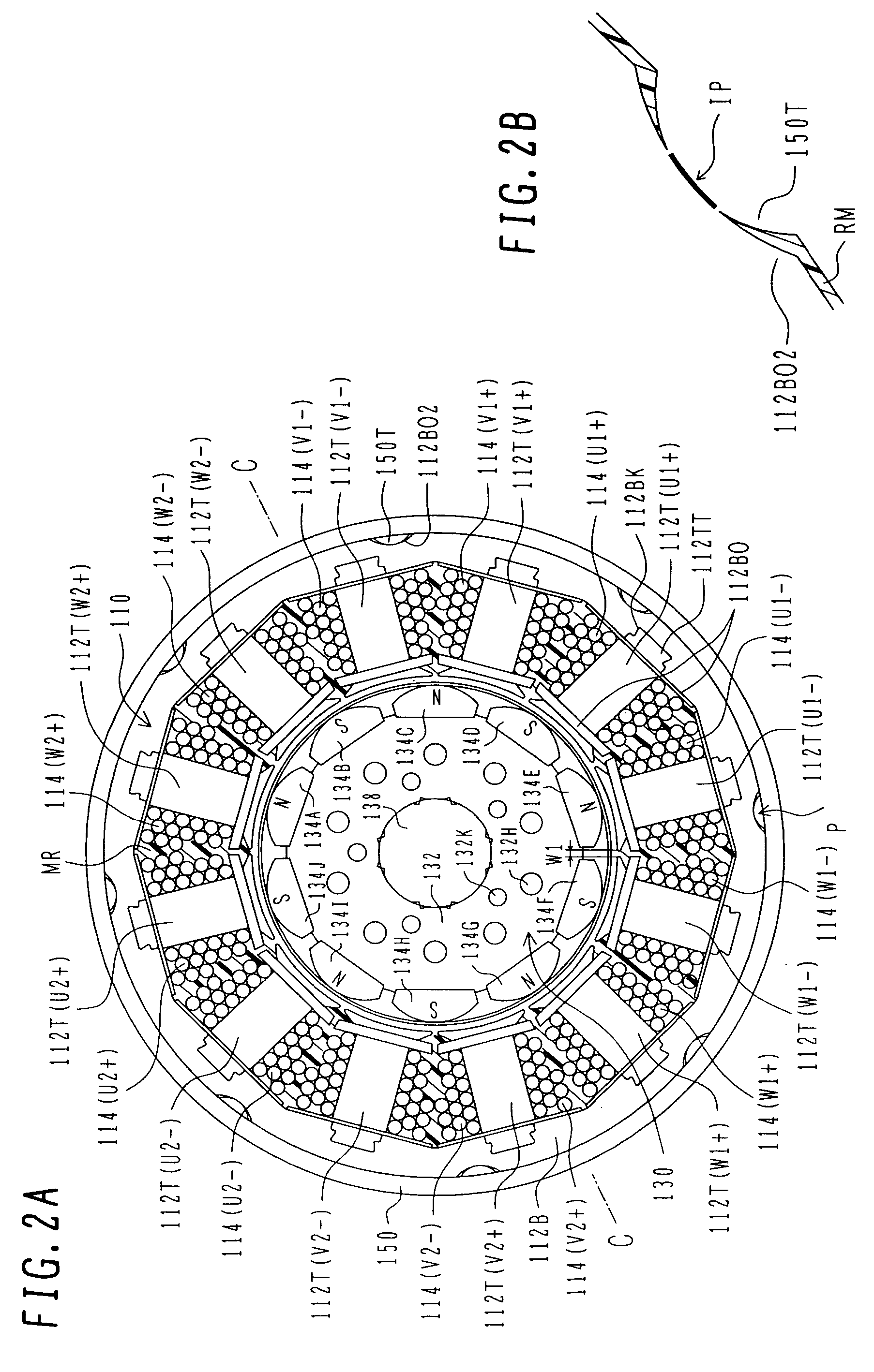
[0034] First, the structure of the motor for electric power steering according to the embodiment will be described with reference to FIGS. 1 and 2.

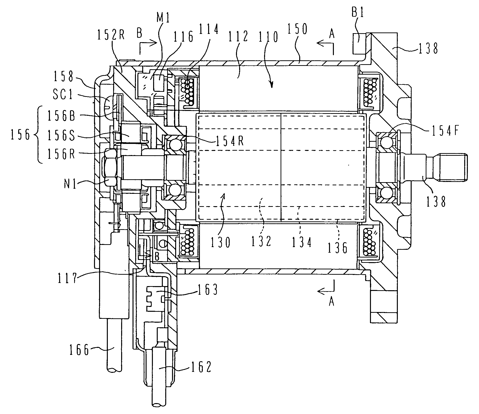
[0035]FIG. 1 is a longitudinal sectional view showing the structure of a motor for electric power steering according to the embodiment. FIGS. 2A and 2B are each a sectional view taken along the line A-A in FIG. 1; specifically, FIG. 2A is an entire sectional view and FIG. 2B is an enlarged sectional view of a principal portion.

[0036] A motor 100 for electric power steering (referred to as an “EPS motor 100” hereinafter) is a synchronous motor of the surface magnet type comprising a stator 110 and a rotor 130 rotatably supported inside the stator 110. The EPS motor 100 is driven by electric power supplied from an onboard power supply including a battery...


PUM


Abstract

A small-sized motor for electric power steering, in which coil connection can be easily performed with space saving, and a method for manufacturing the motor. Multi-phase stator coils assembled in a stator coil are connected per phase by connecting rings at coil ends of the stator coils. A bus bar supplied with electric power from the exterior is stacked onto the connecting rings in the axial direction of the motor and is electrically connected to the connecting rings.

Description

BACKGROUND OF THE INVENTION [0001] 1. Field of the Invention [0002] The present invention relates to a motor for electric power steering and a method for manufacturing the motor. More particularly, the present invention relates to a motor for electric power steering, which is suitable for a motor having multi-phase stator coils and includes connecting members per phase and among phases, and to a method for manufacturing the motor. [0003] 2. Description of the Related Art [0004] In a known motor, winding conductors are interconnected per phase to constitute multi-phase stator coils, and the stator coils are electrically connected to power harnesses per phase. Then, the power harnesses are withdrawn out of the motor. [0005] As disclosed in, e.g., JP-A-2003-134724, there is also known a motor in which winding conductors are interconnected by flat-plate conductors per phase to constitute multi-phase stator coils, and the flat-plate conductors are withdrawn out of the motor. SUMMARY OF T...

Claims


Application Information

Patent Timeline
IPC IPC(8): H02K11/00H02K1/00
CPCH02K3/18H02K3/522H02K2203/09
Inventor YAGAI, MASAMICHIMIRUMACHI, MITSUAKIUEDA, TOSHIAKIONOSE, SHIN
Owner HITACHI LTD
Learn More