Drive method for solid-state imaging device, solid-state imaging device, and imaging apparatus

a solid-state imaging and drive method technology, applied in the direction of instruments, television systems, television system scanning details, etc., can solve the problems of less flexibility, difficulty in maintaining the same color spatial repeat pattern and pitch ratio in the vertical, horizontal, oblique directions, and the color component primary component of generating luminance components, and achieve the spatial frequency characteristics of color components, which are the primary components of generating luminance components, and the effect of high-quality added signals

Inactive Publication Date: 2006-06-29
SONY CORP
View PDF10 Cites 46 Cited by
  • Summary
  • Abstract
  • Description
  • Claims
  • Application Information

AI Technical Summary

Benefits of technology

[0048] According to an embodiment of the present invention, in a solid-state imaging device having an oblique pixel pattern, after adding pixels, the original color pattern can be maintained without changing the color spatial repeat pattern or the pitch ratio in the vertical, horizontal, and oblique directions. As a result, by spatially equal sampling, high-quality added signals can be obtained. At the same time, the added signals can be output in the same color pattern as that obtained by a progressive (all-pixel) reading method for independently reading pixel signals, thereby facilitating the signal processing in the subsequent stage.
[0049] Also, the spatial frequency characteristics of the color components, which are the primary components for generating luminance components, can be increased. Thus, high resolution can be achieved, not only for achromatic color subjects, but also for chromatic color subjects. Additionally, the processing for adjusting the level balance for RGB pixels becomes unnecessary, thereby preventing the occurrence of false colors.

Problems solved by technology

In this reading method, the reading speed is fast since many pixel signals can be read out by one reading operation, but on the other hand, it is necessary that the pixel signals in two adjacent rows be read out at the same time, which is less flexible.
Accordingly, when performing the pixel addition in the color coding of the oblique pixel pattern shown in FIG. 8 generated by shifting the Bayer pattern by 45°, unlike the pixel addition in the color coding in the Bayer pattern, the resulting color pattern of the added signals becomes different from the original color pattern while finding it difficult to maintain the same color spatial repeat pattern and the same pitch ratio in the vertical, horizontal, and oblique directions.

Method used


Image

  • Drive method for solid-state imaging device, solid-state imaging device, and imaging apparatus
  • Drive method for solid-state imaging device, solid-state imaging device, and imaging apparatus
  • Drive method for solid-state imaging device, solid-state imaging device, and imaging apparatus

Examples


first embodiment

[0094]FIG. 11 illustrates the concept of adding pixels by a drive method according to a first embodiment of the present invention. In the color coding of a pixel pattern shifted from the Bayer pattern by 45° in accordance with the oblique pixel pattern, from a 3×3 pixel area, the same color of pixels in the two columns and two rows are extracted and added while shifting the 3×3 pixel area by three pixels, i.e., in units of three pixels. The process of such pixel addition is specifically discussed below.

[0095] In FIG. 11, R pixels 111, 113, 151, and 153 located in the odd-numbered rows are added, and then, the resulting addition R signal is positioned at centroid A. Similarly, by horizontally shifting three pixels from the R pixels 111, 113, 151, and 153, B pixels 114, 116, 154, and 156 are added, and then, the resulting addition B signal is positioned at centroid B. By further horizontally shifting three pixels from the B pixels 114, 116, 154, and 156, R signals 117, 119, 157, and ...

second embodiment

[0098]FIG. 12 illustrates the concept of adding pixels by a drive method according to a second embodiment of the present invention. In the color coding of a pixel pattern shifted from the Bayer pattern by 45° in accordance with the oblique pixel pattern, from a 5×5 pixel area, the same color of pixels in the three columns and three rows are extracted and added while shifting the 5×5 pixel area by three pixels. The process of such pixel addition is specifically discussed below.

[0099] In FIG. 12, R pixels 211, 213, 215, 251, 253, 255, 291, 293, and 295 located in the odd-numbered rows are added, and then, the resulting addition R signal is positioned at centroid A. By horizontally shifting three pixels from the R pixels 211, 213, 215, 251, 253, 255, 291, 293, and 295, B pixels 214, 216, 218, 254, 256, 258, 294, 296, and 298 are added, and then, the resulting addition B signal is positioned at centroid B. By further horizontally shifting three pixels from the B pixels 214, 216, 218, 2...

third embodiment

[0102]FIG. 13 illustrates the concept of adding pixels by a drive method according to a third embodiment of the present invention. In the oblique pixel pattern without a color filter, from a 3×3 pixel area, adjacent pixels in the two columns and two rows are extracted and added while shifting the 3×3 pixel area by three pixels. The process of such pixel addition is specifically discussed below.

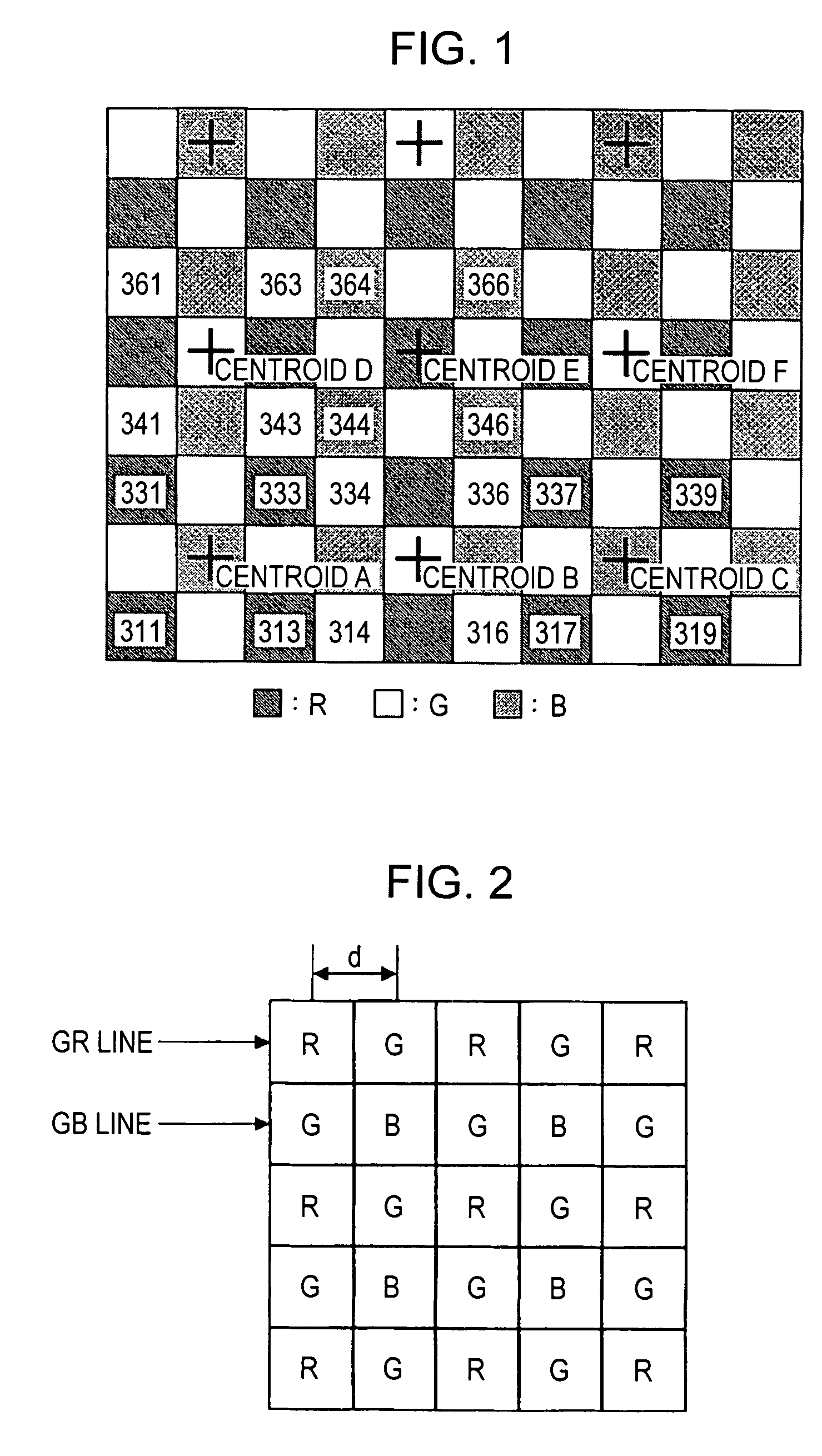
[0103] In FIG. 13, pixels 311, 312, 331, and 332 located in the odd-numbered rows are added, and then, the resulting added signal is positioned at centroid A. By horizontally shifting three pixels from the pixels 311, 312, 331, and 332, pixels 314, 315, 334, and 335 are added, and then, the resulting added signal is positioned at centroid B. By further shifting three pixels from the 314, 315, 334, and 335, pixels 317, 318, 337, and 338 are added, and the resulting added signal is positioned at centroid C.

[0104] Then, by obliquely shifting three pixels, pixels 342, 343, 362, and 363 located i...


PUM


Abstract

A drive method for a solid-state imaging device having an oblique pixel pattern includes the steps of: adding, separately for an odd-numbered row and an even-numbered row, x pixels in the horizontal direction and y pixels in the vertical direction, the x pixels and the y pixels having the same color, in an area having adjacent n pixels in the horizontal direction and adjacent n pixels in the vertical direction, where n is an odd number of three or greater and n≧x≧y; and repeatedly adding the x pixels and the y pixels while shifting the n×n area by m pixels in the vertical or horizontal direction, where m is an odd number of three or greater. The n×n area of odd-numbered rows is displaced from that of even-numbered rows by m pixels in the oblique direction in the oblique pixel pattern.

Description

CROSS REFERENCES TO RELATED APPLICATIONS [0001] The present invention contains subject matter related to Japanese Patent Application JP 2004-375405 filed in the Japanese Patent Office on Dec. 27, 2004, Japanese Patent Application JP 2005-107034 filed in the Japanese Patent Office on Apr. 4, 2005, and Japanese Patent Application JP 2005-107037 filed in the Japanese Patent Office on Apr. 4, 2005, the entire contents of which are incorporated herein by reference. BACKGROUND OF THE INVENTION [0002] 1. Field of the Invention [0003] The present invention relates to a drive method for a solid-state imaging device, a solid-state imaging device, and an imaging apparatus. More particularly, the invention relates to a drive method for an X-Y address solid-state imaging device, a typical example of which is a complementary metal-oxide semiconductor (CMOS) device image sensor, a solid-state imaging device implementing the above drive method, and an imaging apparatus using the solid-state imaging...

Claims


Application Information

Patent Timeline
Patent Type & Authority Applications(United States)
IPC IPC(8): H04N9/04
CPCH04N3/1562H04N9/045H04N25/46H04N25/00H04N23/12
Inventor YOKOTA, KAZUHIDEKUREBAYASHI, HISASHITANAKA, KENJIMATSUI, AKIRAYONEDA, YUTAKAASATO, SEISHINCHIBA, TAKUYAKOSAKAI, RYOTA
Owner SONY CORP
Why Eureka
Try Eureka