Video signal processing device, method of the same and vehicle-mounted camera system

a video signal and camera system technology, applied in the direction of differential synchronisation source locking, signal generator with optical-mechanical scanning, television systems, etc., can solve the problem of increasing the disparity between the actual position of an obstacle and its displayed position, causing the driver an odd feeling or discomfort, and shortening the delay time. , the effect of reducing the memory capacity

Inactive Publication Date: 2006-06-29
NISSAN MOTOR CO LTD
View PDF8 Cites 22 Cited by
  • Summary
  • Abstract
  • Description
  • Claims
  • Application Information

AI Technical Summary

Benefits of technology

[0020] Moreover, with the method of buffering such input video signals to secure the synchronization, there arises a problem that the memory capacity of an input buffer increases and the size of the devices becomes larger, as the number of cameras connected to a camera controller increases.
[0021] The present invention has been made in view of such problems, and an object of the present invention is to provide a video signal processing device in a system where asynchronous images imaged by a plurality of cameras are arranged in the image of one frame, which can shorten a delay time till the image is displayed and a time difference between the images of each camera and also can reduce the memory capacity, and to provide a method of the same.
[0022] In addition, another object of the present invention is to provide a vehicle-mounted camera system which can shorten a delay time till the image is displayed and a time difference between the images of each camera and can present information on the situation surrounding the vehicle to the driver.

Problems solved by technology

However, with the above-mentioned technique, the video signals inputted from the respective cameras are processed frame by frame, and a delay equivalent to approximately two frames (66.6 ms) at the maximum therefore occurs due to the synchronization process between each video signal.
However, if the vehicle-mounted camera system for image display is used in middle to high speed regions such as when moving into an intersection or a T intersection with poor visibility, when vehicles passing each other, or when merging with other traffic, there arises a problem of an increased disparity between the actual position of an obstacle and its displayed position.
In other words, there is a potential that a disagreement between the actual move of the vehicle and the move of the image on the monitor gives the driver an odd feeling or a feeling of discomfort.
This time difference can be the cause that an imaged object is smeared or blurred in the vicinity of a joint, in the case where the images of the cameras are joined together side by side and displayed on one monitor.
Thus, the driver may have a difficulty in recognizing the position of the object.
Additionally, when the moving object around the vehicle moves over the joint of the images on the monitor, there is a potential to cause a phenomenon that the object disappears from the monitor or that the object is appeared as plural objects.

Method used


Image

  • Video signal processing device, method of the same and vehicle-mounted camera system
  • Video signal processing device, method of the same and vehicle-mounted camera system
  • Video signal processing device, method of the same and vehicle-mounted camera system

Examples


first embodiment

[0041] A description will be given of a first embodiment of the present invention with reference to FIGS. 1A to 7.

[0042] Firstly, a description will be given of the outline of a vehicle-mounted camera system for image display of this embodiment.

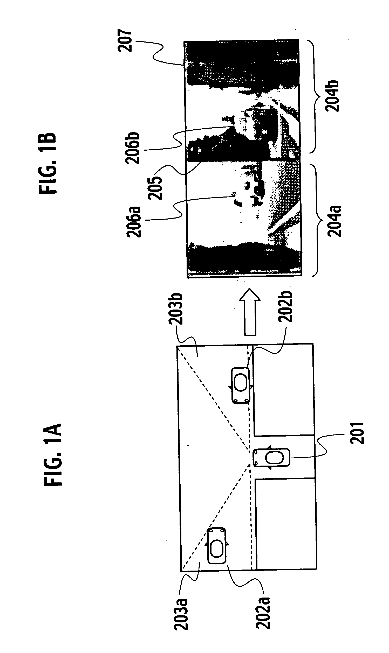
[0043]FIGS. 1A-1B explain the outline of the vehicle-mounted camera system for image display of this embodiment. FIG. 1A schematically shows a vehicle position in a T intersection with poor visibility, and FIG. 1B shows an example of an image presented to the driver by a monitor which is provided for the vehicle-mounted camera system for image display of host vehicle in the situation shown in FIG. 1A.

[0044]FIG. 1A shows a host vehicle 201, a first other vehicle 202a which comes straight from the left of the host vehicle 201, a second other vehicle 202b which comes straight from the right of the host vehicle 201, a first imaging range 203a which is imaged by a camera set up on the left front of the host vehicle 201 (hereinafter, referred to...

second embodiment

[0090] A description will be given of a second embodiment of the present invention with reference to FIGS. 8 to 14.

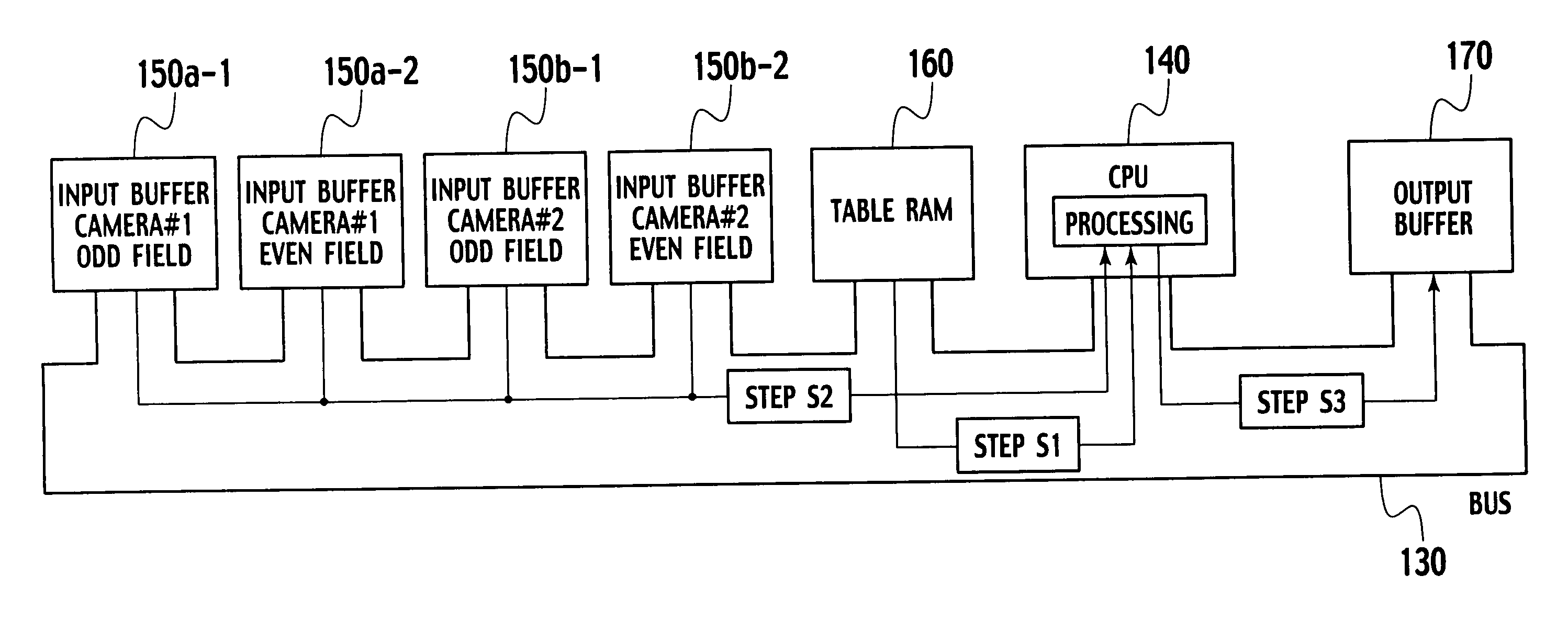
[0091] It is possible to shorten the maximum delay time from the imaging to the display with the above-mentioned vehicle-mounted camera system for image display 100 of the first embodiment. However, as shown in FIG. 6, the difference in the imaging timing between the simultaneously displayed images of the cameras #1 and #2, that is, the time difference of each camera image is approximately 33.3 ms at the maximum, which is equivalent to the difference between the time t1 and the time t2. The time difference of each camera image in the method of performing the address conversion processing frame by frame, too, is approximately 33.3 ms at the maximum as shown in FIG. 7. Regarding this point, the vehicle-mounted camera system for image display 100 of the first embodiment is not improved.

[0092] A description will be given of a vehicle-mounted camera system for image displa...

third embodiment

[0127] A description will be given of a third embodiment of the present invention with reference to FIGS. 13 and 14.

[0128] A vehicle-mounted camera system for image display of the third embodiment is one in which the method of address conversion processing of the vehicle-mounted camera system for image display of the second embodiment is modified.

[0129]FIG. 13 is a flowchart showing address conversion processing of a camera controller in the third embodiment.

[0130] A CPU 140 targets a plurality of temporally closest camera input data for the address conversion. Additionally, these of the field image data are monitored whether to be the odd- or even-numbered field data of an original camera image (Step S31).

[0131] After the synchronization of the input field data, the CPU 140 determines whether the odd-numbered field data of the output data matches the odd- and even-numbered field data of the camera input field data (Step S32).

[0132] When matched, the CPU 140 performs the addres...


PUM


Abstract

A video signal processing device, which includes: a plurality of imaging devices outputting mutually asynchronous interlace video signals; input buffers temporarily storing field by field the video signals outputted from the respective imaging devices; and an output image generating device generating field by field video signals of output target images from the video signals stored in the input buffers, wherein each of the video signals of the output target images is generated when all of the latest video signals to be components thereof are stored in the input buffers.

Description

BACKGROUND OF THE INVENTION [0001] 1. Field of the Invention [0002] The present invention relates to a video signal processing device for synthesizing a plurality of interlace video signals which are asynchronous to each other and generating output video signals, and a method of the same, and relates to a vehicle-mounted camera system applying the video signal processing device, which is a system mounted on a vehicle and the like, for imaging areas around the vehicle in different directions with a plurality of cameras and displaying the images for the driver thereof. [0003] 2. Description of Related Art [0004] A vehicle-mounted camera system for image display is a driving support system for presenting a driver with an additional visual information in cases where a vehicle is moving backward and forward, such as when parking a vehicle in a garage and when pulling over to the kerb, or where a vehicle is moving into an intersection or a T intersection with poor visibility. In this syst...

Claims


Application Information

Patent Timeline
Patent Type & Authority Applications(United States)
IPC IPC(8): H04N5/04H04N9/475H04N11/08H04N9/44
CPCB60R1/00B60R2300/105B60R2300/30B60R2300/802B60R2300/8066H04N5/2624
Inventor SUZUKI, MASAYASUAKATSUKA, TAKESHI
Owner NISSAN MOTOR CO LTD
Why Eureka
Try Eureka