
Exposure apparatus and device fabricating method

a technology of device fabrication and exposure apparatus, which is applied in the direction of photomechanical equipment, instruments, printers, etc., can solve the problems of insufficient focus margin, adversely affecting the pattern formed on the substrate, and liquid in these immersion areas will not be sufficiently recovered

Active Publication Date: 2006-06-29
NIKON CORP
View PDF99 Cites 56 Cited by
  • Summary
  • Abstract
  • Description
  • Claims
  • Application Information

AI Technical Summary

Benefits of technology

[0012] The present invention was made considering such circumstances, and it is an object of the present invention to provide an exposure apparatus that can sufficiently remove and / or recover unnecessary liquid and form a desired device pattern on the substrate when projecting and exposing a pattern onto a substrate through a projection optical system and liquid, and a device fabricating method that uses this exposure apparatus.

Problems solved by technology

If the depth of focus δ becomes excessively narrow, then it will become difficult to align the surface of the substrate with the image plane of the projection optical system, and there will be a risk of insufficient margin of focus during the exposure operation.
In addition, if liquid remains on the optical element at the front of the projection optical system, then there is a possibility that adhered residue (a so-called water mark) will be left on the optical element at the front of the projection optical system after this remaining liquid has vaporized, and will adversely affect the pattern formed on the substrate when performing the next exposure process.
In addition, it is conceivable that immersion areas will form, even when not performing the exposure process, when using a reference plane member, a fiducial mark member, and the like, disposed around the substrate on the substrate stage, and there is a possibility that the liquid in these immersion areas will not be sufficiently recovered and that adhered residue will be left on these members, or that the liquid remaining on these members will scatter.
If the liquid scattered from the substrate during exposure adheres to, for example, the reflecting mirror for each of the stage interferometers, then there is a risk that it will degrade the accuracy of the stage position measured by the interferometer.

Method used


Image

  • Exposure apparatus and device fabricating method
  • Exposure apparatus and device fabricating method
  • Exposure apparatus and device fabricating method

Examples


Embodiment Construction

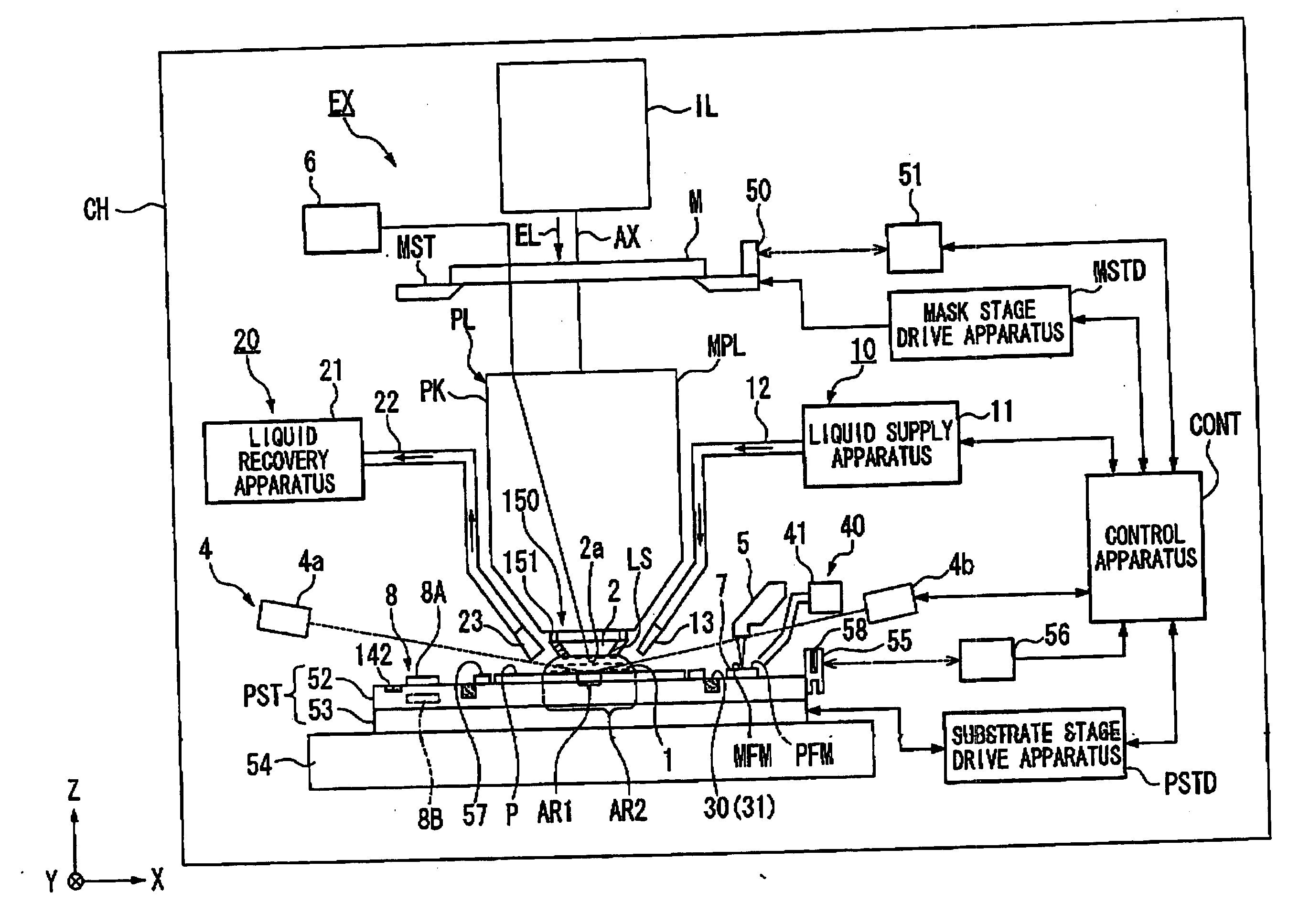
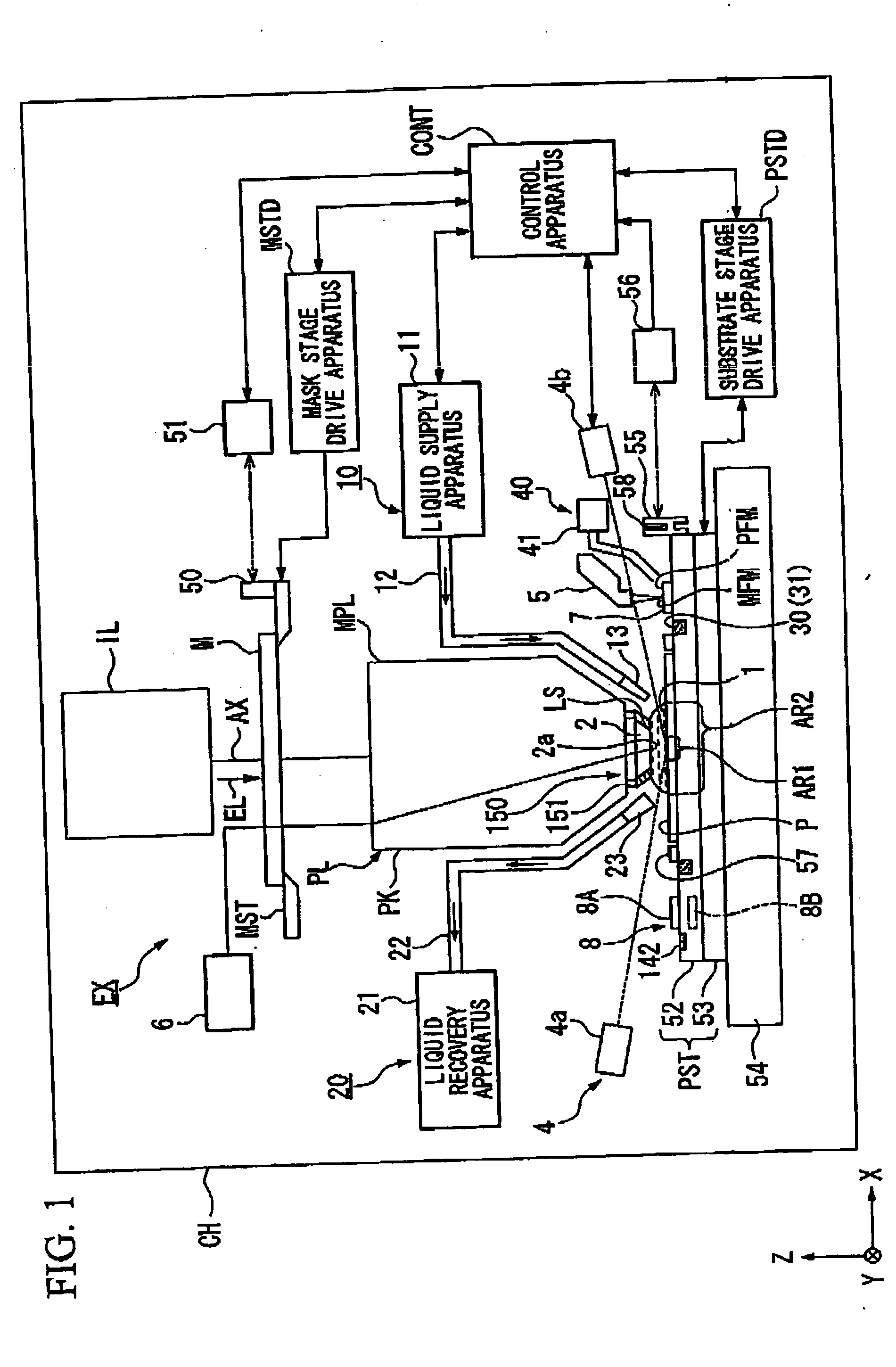
[0055] The following explains the exposure apparatus of the present invention, referencing the drawings. FIG. 1 is a schematic block diagram that depicts one embodiment of the exposure apparatus according to the present invention.

[0056] In FIG. 1, the exposure apparatus EX includes: a mask stage MST that supports a mask M; a substrate stage PST that supports a substrate P; an illumination optical system IL that illuminates with an exposure light EL the mask M supported by the mask stage MST; a projection optical system PL that projects and exposes a pattern image of the mask M illuminated by the exposure light EL onto the substrate P supported by the substrate stage PST; and a control apparatus CONT that provides overall control of the operation of the entire exposure apparatus EX. The entire exposure apparatus EX is housed within a chamber apparatus CH.

[0057] The exposure apparatus EX of the present embodiment is a liquid immersion type exposure apparatus that applies the liquid ...


PUM


Abstract

An exposure apparatus exposes a substrate by filling a liquid between a projection optical system and the substrate, and projecting the image of a pattern onto the substrate through the projection optical system and the liquid, and includes a liquid removing mechanism that intermittently blows a gas against a reference member, movable mirror, and the like, to which the liquid is adhered in order to remove that liquid.

Description

CROSS-REFERENCE TO RELATED APPLICATION [0001] This is a Continuation Application of International Application No. PCT / JP2004 / 012795, filed Aug. 27, 2004, which claims priority to Japanese Patent Application No. 2003-307025 (filed Aug. 29, 2003). The contents of the aforementioned application are incorporated herein by reference.BACKGROUND OF THE INVENTION [0002] 1. Field of the Invention [0003] The present invention relates to an exposure apparatus, which exposes a pattern on a substrate through a projection optical system and a liquid, and a device fabricating method. [0004] 2. Description of Related Art [0005] Semiconductor devices and liquid crystal display devices are fabricated by a so-called photolithography technique, wherein a pattern formed on a mask is transferred onto a photosensitive substrate. An exposure apparatus used by this photolithographic process includes a mask stage that supports the mask, and a substrate stage that supports the substrate, and transfers the pat...

Claims


Application Information

Patent Timeline
IPC IPC(8): G03B27/42G03B27/52G03F7/20H01L21/027
CPCG03F7/70341G03F7/70916
Inventor HARA, HIDEAKITAKAIWA, HIROAKI
Owner NIKON CORP
Learn More