Terminal-equipped wire and method for manufacturing the same

Active Publication Date: 2015-08-13
YAZAKI CORP
View PDF3 Cites 8 Cited by
  • Summary
  • Abstract
  • Description
  • Claims
  • Application Information

AI Technical Summary

Benefits of technology

The invention provides a terminal fitting for electric wires that includes a grip and a projection that penetrates the insulating coating of the wire. This eliminates the need for removing the insulating coating at the terminal section of the wire. The grip prevents water from entering the insulating coating and the conductor, reducing the risk of corrosion and increasing the lifespan of the wire. The invention also includes different forms of the projection that can be selected based on the installation location, improving waterproof performance and reducing production costs. Overall, the invention prevents water from reaching the contact points between the projection and the conductor, improving the corrosion resistance of the terminal-equipped wire.

Problems solved by technology

On the other hand, because the exposed conductor and the front leg of the terminal fitting closely contact each other in a pressure condition, when the water or a chemical attach to this connection portion, galvanic corrosion may be generated in the conductor or the terminal fitting to deteriorate the terminal-equipped wire.

Method used


Image

  • Terminal-equipped wire and method for manufacturing the same
  • Terminal-equipped wire and method for manufacturing the same
  • Terminal-equipped wire and method for manufacturing the same

Examples


first embodiment

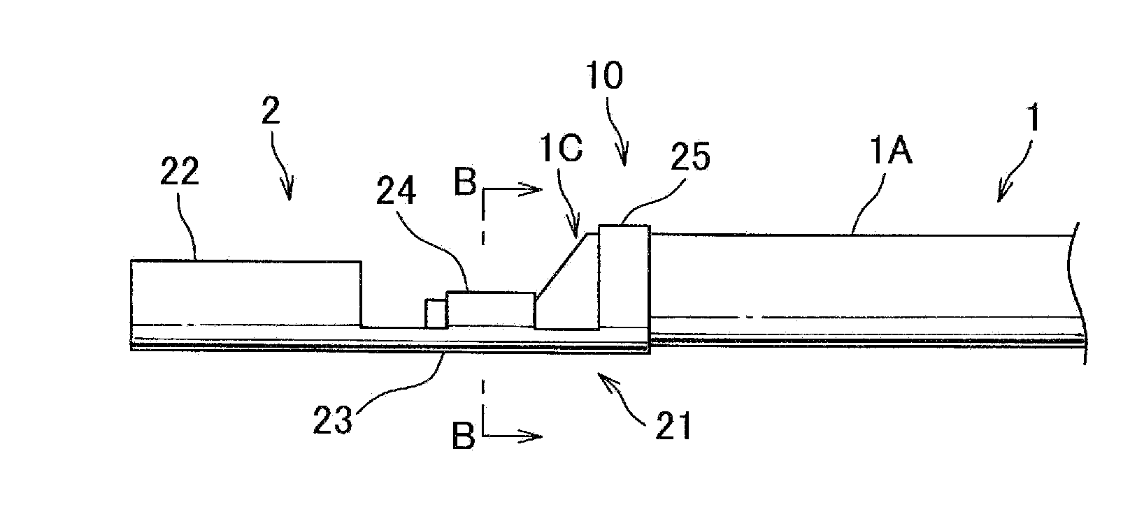
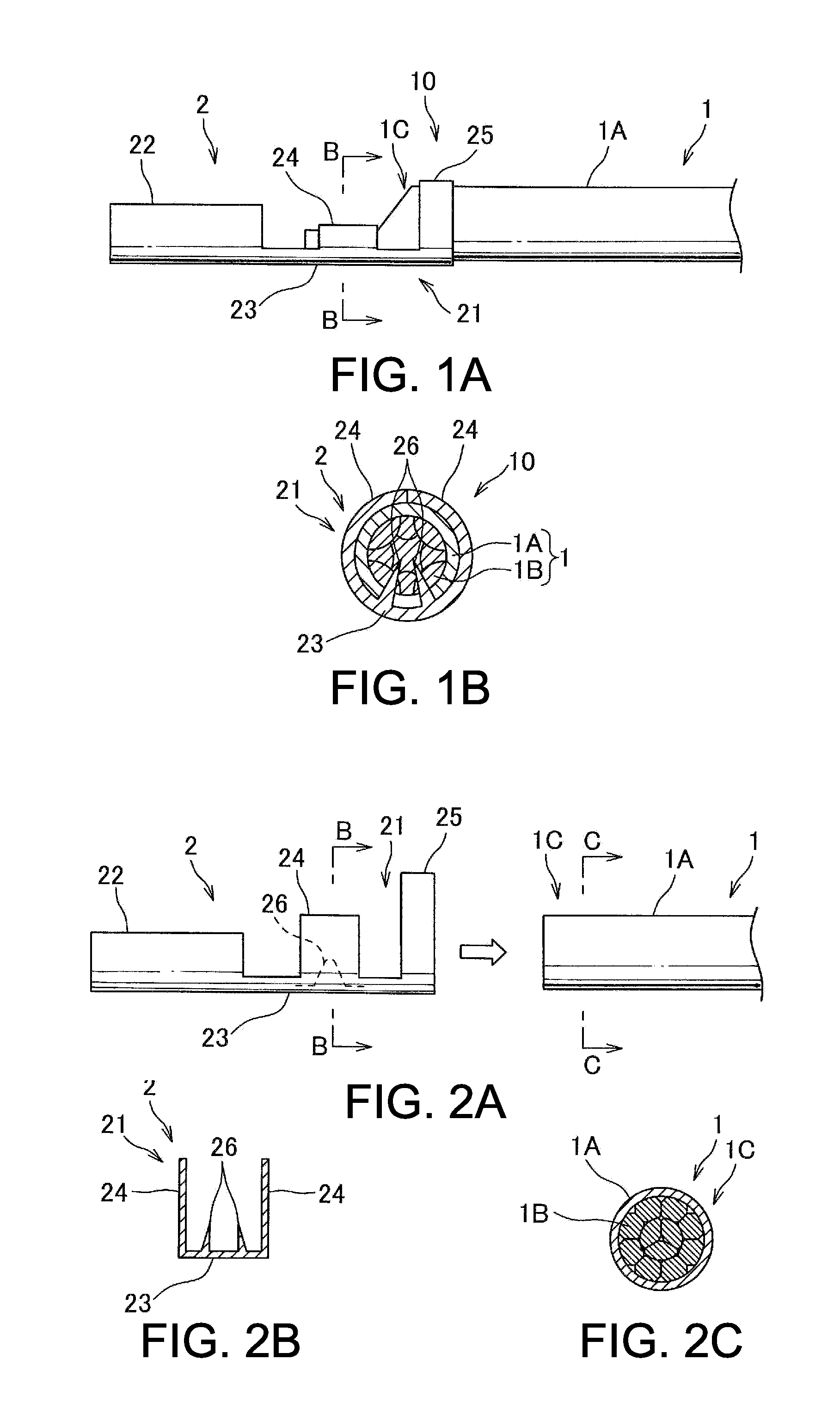
[0038]A terminal-equipped wire according to a first embodiment of the present invention will be explained with reference to FIGS. 1A to 3B. A terminal-equipped wire 10 according to the first embodiment is, for example, a component of a wiring harness connecting on-vehicle electronic devices to each other, and includes: an electric wire 1 having a conductor 1B in an insulating coating 1A; and a terminal fitting 2 crimped to a terminal section 1C of this electric wire 1. The conductor 1B of the electric wire 1 is, for example, a stranded wire made by twisting a plurality of element wires. As the element wire, for example, an annealed copper wire made of copper, copper alloy, a tin-plated copper wire, a nickel-plated copper wire, and an aluminum wire made of aluminum alloy can be used.

[0039]As shown in FIGS. 1A to 2C, the terminal fitting 2 is a female terminal made by folding a copper or copper alloy plate or the like, and includes: a wire connection portion 21 connected to the electr...

second embodiment

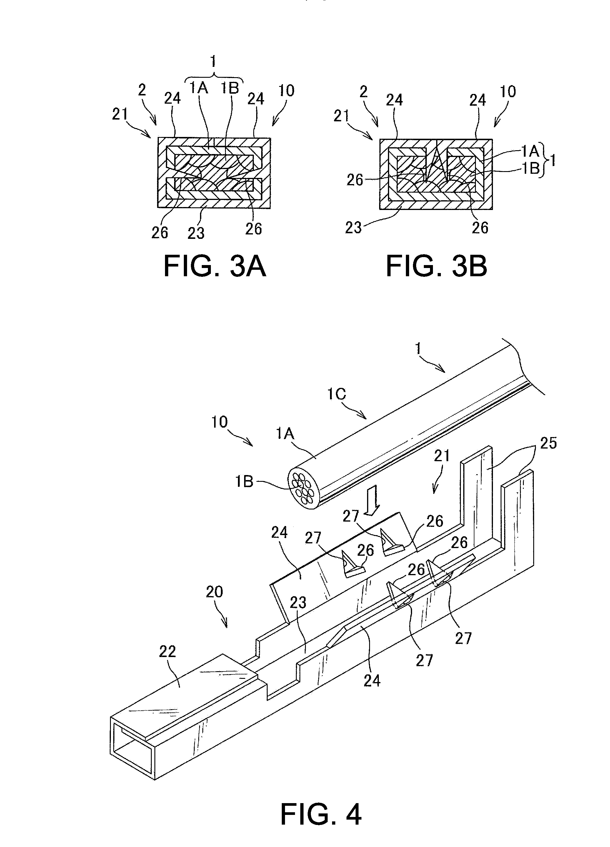
[0044]A terminal-equipped wire according to a second embodiment of the present invention will be explained with reference to FIGS. 4 to 6. A terminal-equipped wire 10 according to this embodiment is different from that according to the first embodiment at a point that the projections 26 are made by notching and folding the front legs 24 of the terminal fitting 2. Hereafter, the difference will be explained in detail.

[0045]As shown in FIG. 4, each of the pair of front legs 24 is provided with two notches 27 at opposite positions, and each of these notches 27 is formed by two sides of an isosceles triangle of which a vertex is positioned toward a tip of the front leg 24. Then, the notch 27 of the two sides is folded inward in an opposite direction of the front legs 24 to form the projection 26. As shown in FIGS. 5A to 5C, in a method for manufacturing the terminal-equipped wire 10 using this terminal fitting 2, a lower die D1 and an upper die D2 are used for connecting the electric wi...

third embodiment

[0048]A terminal-equipped wire according to a third embodiment of the present invention will be explained with reference to FIGS. 7A to 8D. A terminal-equipped wire 10 according to this embodiment is different from those according to the first and second embodiments at a point that the projections 26 are not formed on the terminal fitting 2, a cap member 3 independent from the terminal fitting 2 is provided, a projection 33 is formed on the cap member 3, and the conductor 1B of the electric wire 1 and the terminal fitting 2 are electrically connected to each other via the projection 33 of the cap member 3. Hereinafter, the difference will be explained in detail.

[0049]The cap member 3 is made of conductive metal, and includes: a cylindrical cap main body 31 allowing the terminal section 1C of the electric wire 1 to be inserted thereinto; a bottom portion 32 covering one end of the cap main body 31; and a plurality of projections 33 projected from an inner wall of the cap main body 31...


PUM


Abstract

There is provided a terminal-equipped wire able to reduce a production cost and satisfy water proof and corrosion proof performances at a terminal section of the electric wire. The terminal-equipped wire includes: an electric wire having a conductor in an insulating coating; and a terminal fitting crimped to a terminal section of the electric wire. The terminal fitting includes: an electrical contact portion for connecting with a terminal fitting of the mating connector; and a wire connection portion for connecting with the terminal section of the electric wire continuing to the electrical contact portion. The wire connection portion includes: a grip for gripping the terminal section of the electric wire along a circumferential direction of the electric wire; and a projection penetrating the insulating coating. The conductor and the terminal fitting have electrical continuity with each other via the projection.

Description

TECHNICAL FIELD[0001]The present invention relates to a terminal terminal-equipped wire, and a method for manufacturing a terminal-equipped wire, in particular, to a terminal-equipped wire having a conductor in an insulating coating and a terminal fitting crimped to a terminal section of this electric wire, and a method for manufacturing this terminal-equipped wire.BACKGROUND ART[0002]Conventionally, various electronic devices are mounted on a vehicle or the like, and a wiring harness is arranged therein for transmitting electric power, a control signal, and the like. The wiring harness includes: a plurality of electric wires; terminal fittings attached to terminal sections of the electric wires; and a connector receiving the terminal fittings. When this connector is fitted with a mating connector, the terminal fittings of both connectors are electrically connected to each other, and the electronic devices are connected by the wiring harness. The terminal fitting is made by folding ...

Claims


Application Information

Patent Timeline
IPC IPC(8): H01R4/18H01R43/048
CPCH01R43/048H01R4/183H01R4/185H01R4/2404H01R4/62H01R43/01H01R4/22Y10T29/49185H01R4/2406
Inventor UCHIDA, NAONARIISHIUCHI, HIROSHI
Owner YAZAKI CORP
Why Eureka
Try Eureka