Isolated bidirectional DC-DC converter
a dc-dc converter and bi-directional technology, applied in the direction of instruments, base element modifications, emergency protective arrangements for limiting excess voltage/current, etc., can solve the problems of enlargement of the apparatus and reduce efficiency, and achieve the effect of miniaturization highly efficient and loss due to the circulating current when buck mode can be reduced
- Summary
- Abstract
- Description
- Claims
- Application Information
AI Technical Summary
Benefits of technology
Problems solved by technology
Method used
Image
Examples
embodiment 1
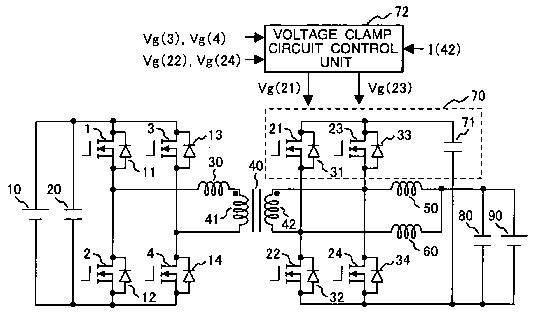
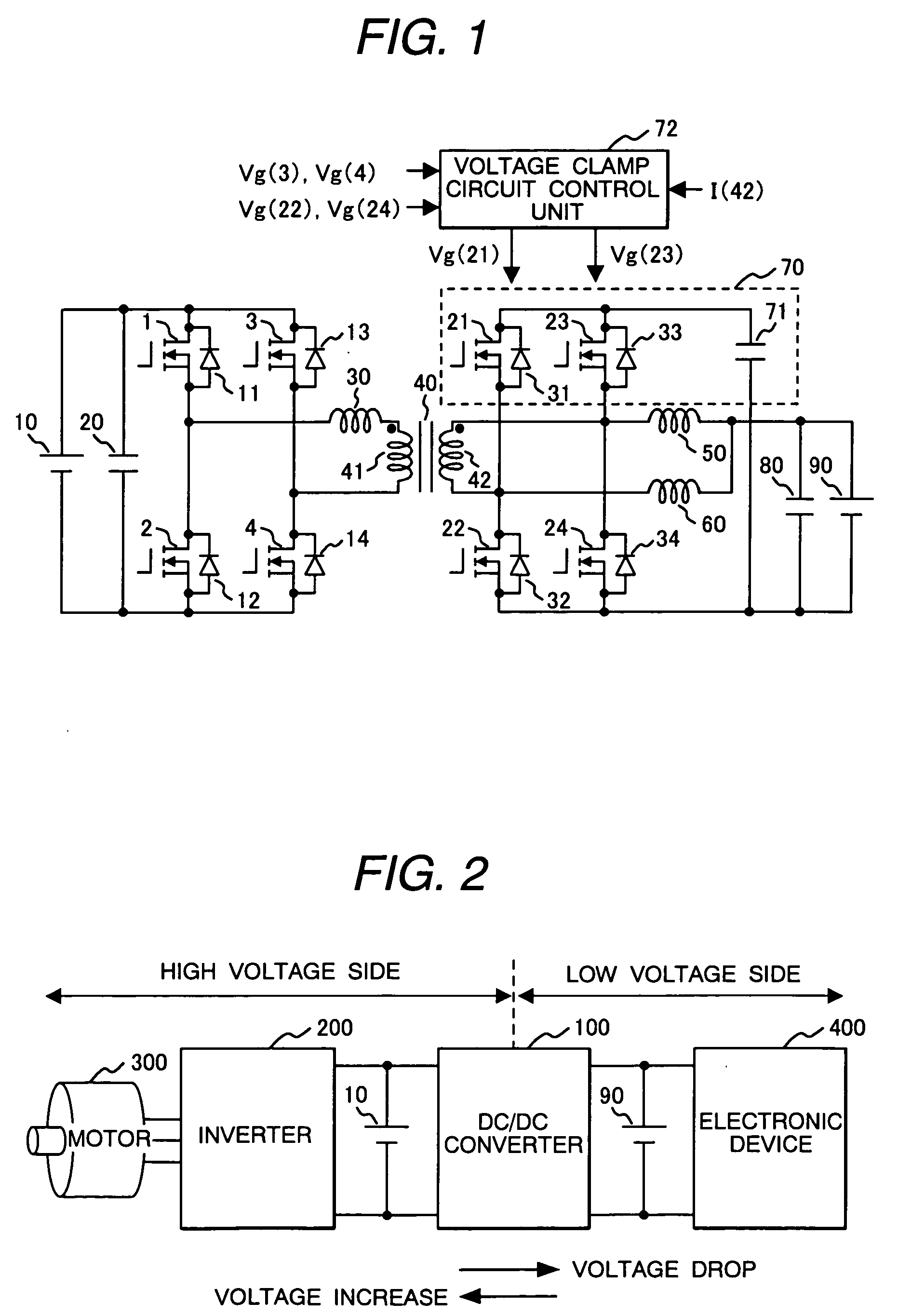
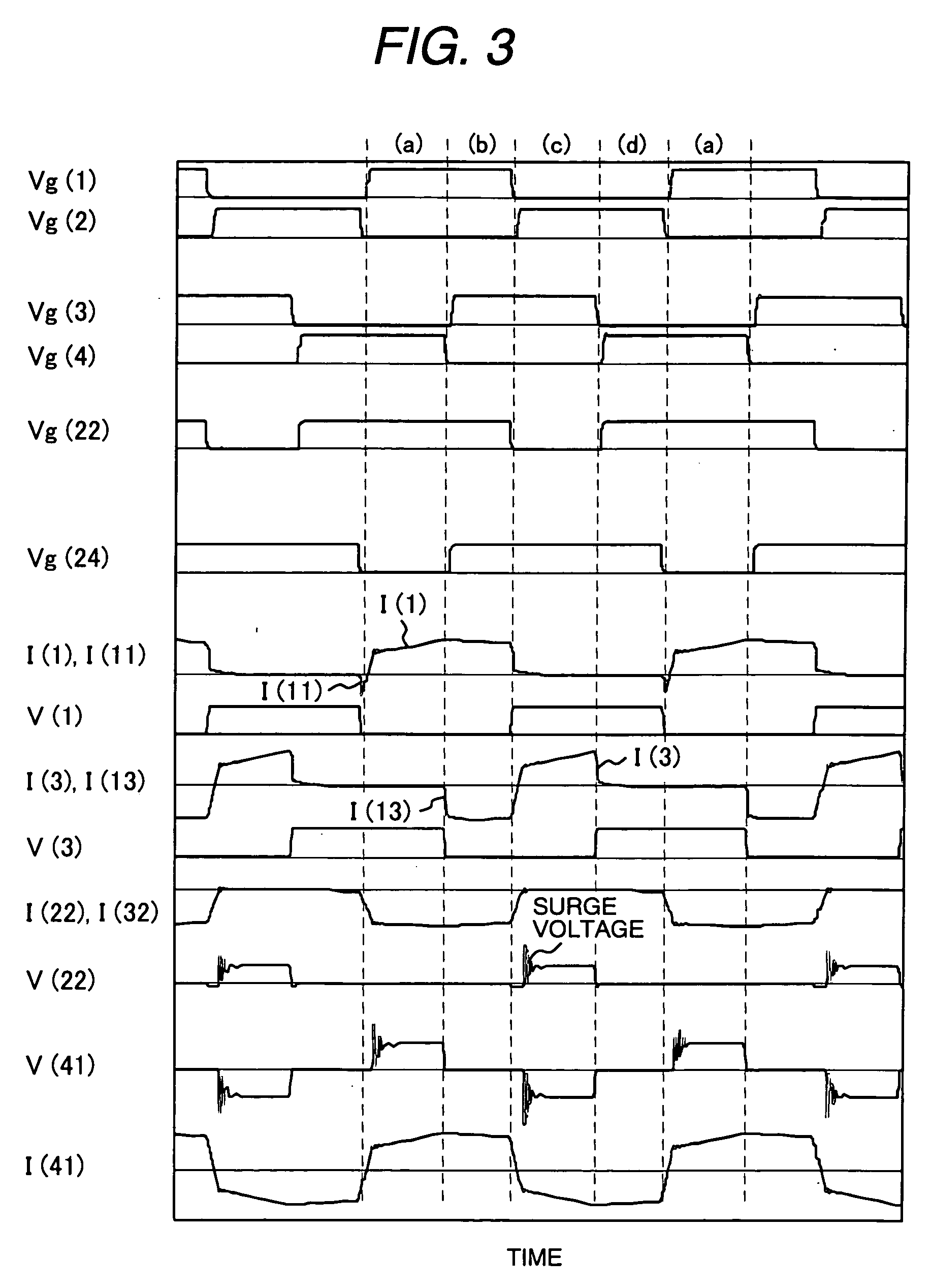
[0026]FIG. 1 is a circuit block diagram of the two-way insulating DC-DC converter of the first embodiment of the present invention. In the drawing, to a DC power source 10 on the high voltage side, a smoothing condenser 20 and a load (not drawn), a first switching arm composed of switching devices 1 and 2 connected in series, and a second switching arm composed of switching devices 3 and 4 connected in series are connected in parallel. To the switching devices 1 to 4, free wheel diodes 11 to 14 are respectively connected in reverse parallel and when the switching devices 1 to 4 are MOSFETs, a body diode can be used. The first and second switching arms are connected to the DC power source 10 in parallel, so that a voltage switching circuit is formed and between the AC terminals of the switching circuit, a primary winding 41 of a transformer 40 is connected via an auxiliary reactor 30. The auxiliary reactor 30, when inverting the polarity of the current flowing through the switching c...
embodiment 2
[0056]FIG. 8 is a circuit block diagram of the two-way insulating DC-DC converter of the second embodiment of the present invention. To the same parts as those shown in FIG. 1, the same numerals are assigned and the explanation will be omitted. In FIG. 8, the difference on the basic circuit from FIG. 1 is that a center tap is installed on the secondary winding 42 of the transformer 40, and the reactor 50 is connected between the center tap and the positive pole of the DC power source 90, and the reactor 60 is removed. By doing this, the voltage clamp circuit 70 is composed of only one series unit of the switching device 23 with the reverse parallel diode 33 and the clamp condenser 71 and the number of parts can be reduced. The switching device 23 is driven by the voltage clamp circuit control unit 74 and is controlled in switching.
[0057]FIG. 9 is a drive voltage waveform diagram of each switching device at the time of buck of the second embodiment of the present invention. In the d...
embodiment 3
[0065] When the two-way insulating DC-DC converter of the present invention, for example, is used in a power source system for a car, it must be mounted in a limited space, so that a request for miniaturization is increased and a stable operation in a high-temperature environment is required. Therefore, as a converter, miniaturization of the transformer and reactor by realization of high frequency, reduction in the on loss of the switching devices and the number of switching devices, and improvement of the cooling method are required.
[0066]FIG. 11 is a circuit block diagram of the two-way insulating DC-DC converter of the third embodiment of the present invention. The difference from Embodiment 1 shown in FIG. 1 is that a static induction transistor (SIT) and an SiC diode using a silicon carbide (SiC) composition material are used. SiC-SIT, compared with the switching devices using a silicone composition material, has excellent characteristics in both aspects of the on resistance a...
PUM
 Abstract
Description
Claims
Application Information
 - R&D
- Intellectual Property
- Life Sciences
- Materials
- Tech Scout
- Unparalleled Data Quality
- Higher Quality Content
- 60% Fewer Hallucinations
Browse by: Latest US Patents, China's latest patents, Technical Efficacy Thesaurus, Application Domain, Technology Topic, Popular Technical Reports.
© 2025 PatSnap. All rights reserved.Legal|Privacy policy|Modern Slavery Act Transparency Statement|Sitemap|About US| Contact US: help@patsnap.com


