Constant current relay drive circuit

a relay drive and constant current technology, applied in relays, basic electric elements, electric devices, etc., can solve the problems of power loss, increase in power consumption and heat generation in the relay drive section, and high drop, so as to reduce power consumption and heat value

Inactive Publication Date: 2006-06-29
ANDEN CORP +1
View PDF3 Cites 28 Cited by
  • Summary
  • Abstract
  • Description
  • Claims
  • Application Information

AI Technical Summary

Benefits of technology

[0013] The constant voltage for providing the constant current is lower than the power supply voltage. Therefore, power consumption and heat value can be reduced.

Problems solved by technology

A constant voltage of 6 volts is needed to generate the magnetomotive force P, when the ambient temperature reaches the maximum temperature of 120° C. However, when the ambient temperature does not reach the maximum temperature, the constant voltage of 6 volts generates excessive magnetomotive force, thereby resulting in loss of power.
However, when the ambient temperature exceeds a threshold temperature T, the constant voltage of 4.3 volts cannot generate the magnetomotive force P so that the relay contact is opened due to lack of magnetomotive force.
However, the voltage drop may be high so that power consumption and heat generation in the relay drive section may be increased.

Method used


Image

  • Constant current relay drive circuit
  • Constant current relay drive circuit
  • Constant current relay drive circuit

Examples


first embodiment

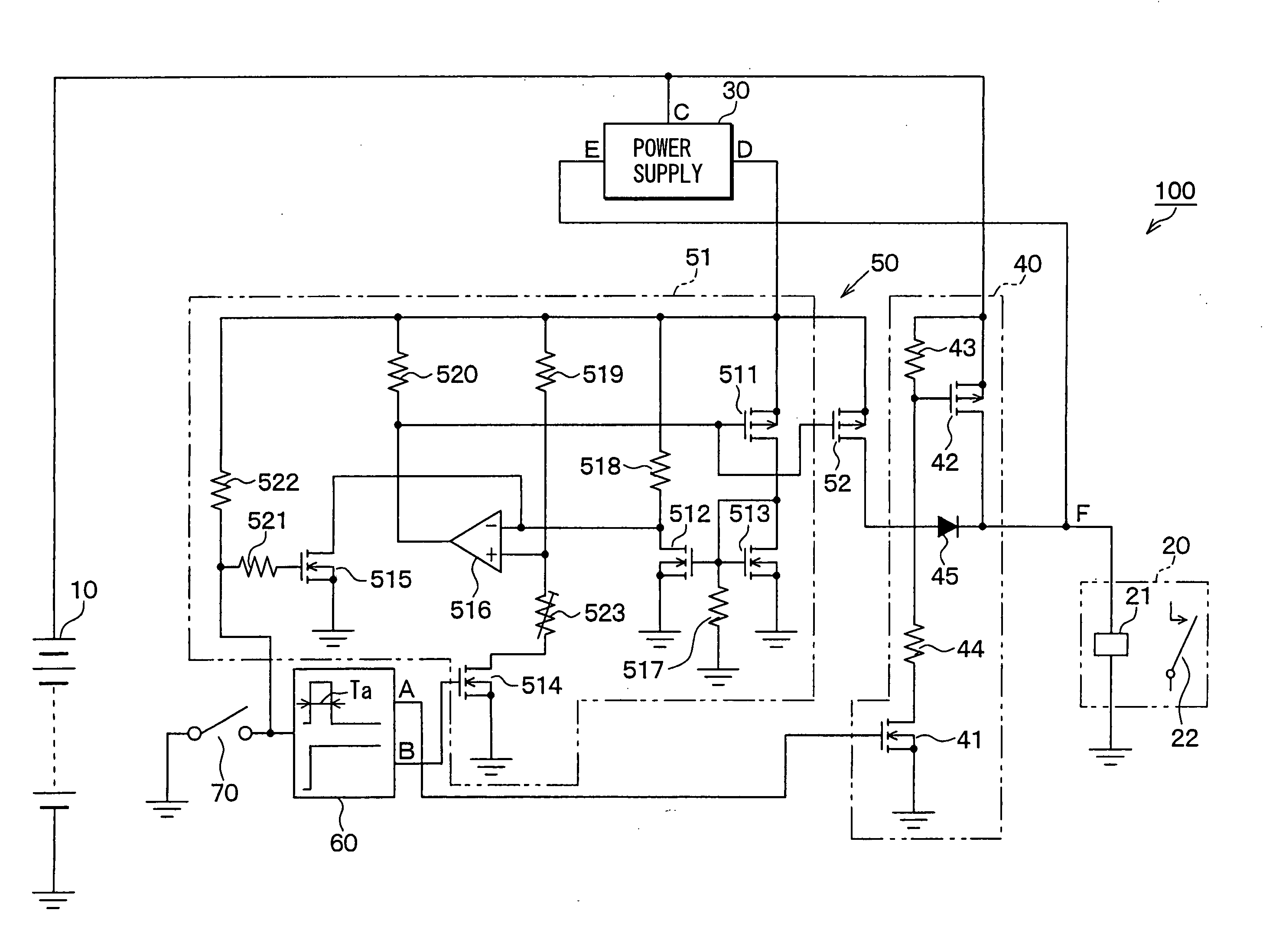
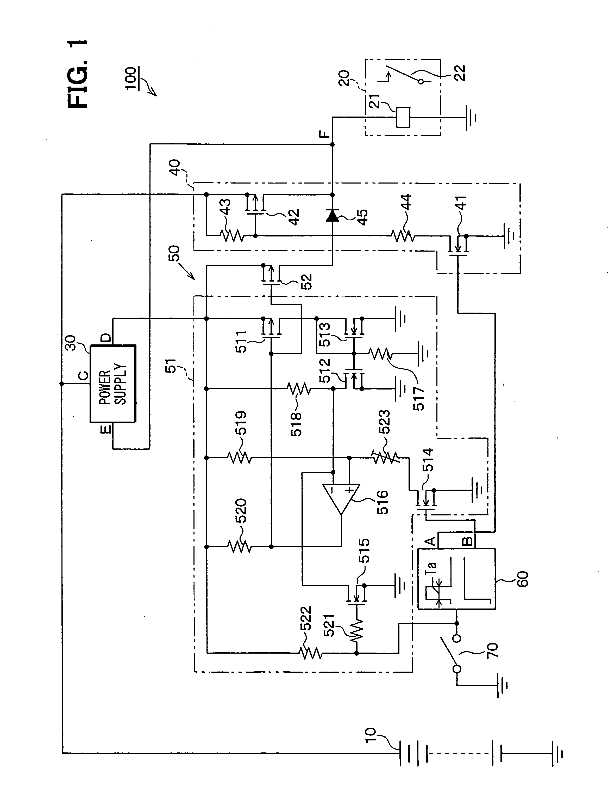
[0023] Reference is made to FIG. 1, which shows a circuit diagram of a relay drive circuit 100. The relay drive circuit 100 is for driving a relay 20 for energizing a load (i.e., vehicular headlight). The relay 20 has a relay coil 21 and a relay contact 22.

[0024] The relay drive circuit 100 includes a power supply circuit 30 for a low-holding energization, an initial energization circuit 40, a low-holding energization circuit 50, and a control circuit 60.

[0025] The power supply circuit 30 produces a constant voltage (e.g., 4 to 6.5 volts) lower than a voltage (12 volts) of a battery 10. The initial energization circuit 40 performs an initial energization such that the battery 10 provides an initial energizing voltage to the relay coil 21 to hold the relay contact 22 in a closed position. The low-holding energization circuit 50 performs the low-holding energization such that the constant voltage provides a constant current to the relay 20 to hold the relay contact 22 in a closed po...

second embodiment

[0061] Reference is made to FIG. 5, which shows a circuit diagram of a relay drive circuit 300. The relay drive circuit 300 has multiple relay drive circuits (hereinafter, “drive channels”) for driving multiple relays 20.

[0062] The relay drive circuit 300 includes a power supply circuit 30, a power supply switching circuit 110, a reference constant current circuit 120, a control circuit 130, and a feedback circuit 140. The relay drive circuit 300 further includes, initial energization circuits 150, low-holding energization circuits 160, relay-off circuits 170, and relay drive transistors 180, which are provided to each drive channel of the respective relays 20.

[0063] The initial energization circuit 150, the low-holding energization circuit 160, and the relay-off circuit 170 are each configured as an analog switch. When the circuits 150-170 receive a control signal of a high level from the control circuit 130, there is conduction between the input and the output of the respective ...


PUM


Abstract

A relay drive circuit includes a power supply circuit for producing a constant voltage, an initial energization circuit for performing an initial energization such that a power supply provides an initial energizing voltage to a relay, a low-holding energization circuit for performing a low-holding energization such that the constant voltage provides a constant current to the relay after the initial energizattion. Due to the low-holding energization, the relay contact can be firmly held even when relay coil resistance changes. The constant voltage for performing the low-holding energization is lower than the power supply voltage so that power consumption and heat generation can be reduced.

Description

CROSS REFERENCE TO RELATED APPLICATION [0001] This application is based on and incorporates herein by reference Japanese Patent Application No. 2004-379805 filed on Dec. 28, 2004. FIELD OF THE INVENTION [0002] The present invention relates to a constant current relay drive circuit. BACKGROUND OF THE INVENTION [0003] A conventional relay drive circuit drives a relay by a constant voltage, thus holding a relay contact in a closed position. However, in such a relay drive circuit, a holding force for holding a relay contact in a closed position depends on magnetomotive force (MMF) of a relay. The magnetomotive force is determined as a product of the number of turns of a relay coil and the amount of electric current flowing through the relay coil. [0004] As understood from FIG. 8, which shows relationships between ambient temperature of the relay and magnetomotive force of the relay, and between the ambient temperature and a relay coil resistance, when the ambient temperature increases, ...

Claims


Application Information

Patent Timeline
Patent Type & Authority Applications(United States)
IPC IPC(8): H01H47/00
CPCH01H47/002H01H47/04H01H2047/025
Inventor SATO, KOICHITSUKADA, KOICHIISHIKAWA, FUKUOMOKUYA, HIROFUMI
Owner ANDEN CORP
Why Eureka
Try Eureka