Power device

Inactive Publication Date: 2006-06-29
TELEFON AB LM ERICSSON (PUBL)
View PDF7 Cites 6 Cited by
  • Summary
  • Abstract
  • Description
  • Claims
  • Application Information

AI Technical Summary

Benefits of technology

[0003] There is thus a need for a device which can convert a first DC-voltage level to a second DC-voltage level, with the device being able to handle rather high power levels, while at the same time occupying a minimal amount of space. In addition, the device should be capable of delivering a stable output voltage regardless of variations in the load connected to the device.
[0004] This need is met by the present invention in that the invention discloses a power device comprising at least a first and a second DC-DC-converter, with each converter having respective input and output voltages, and respective input and output currents, each converter converting an input DC-voltage level to an output DC-voltage level, with each converter also comprising input means for a control signal. The device additionally comprises a control means, and the control means are common to the first and second converters and arranged to detect a first output voltage at a point

Problems solved by technology

However, traditionally when there has been a need for a conversion involving rather high power levels, the tendency has been to use converters which are also larger physically.
In applications where there

Method used


Image

  • Power device
  • Power device

Examples


Embodiment Construction

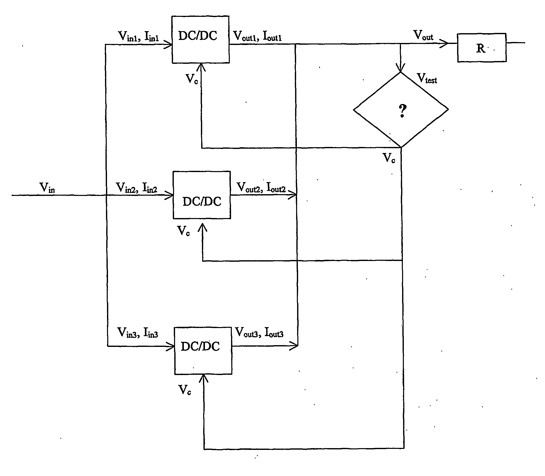
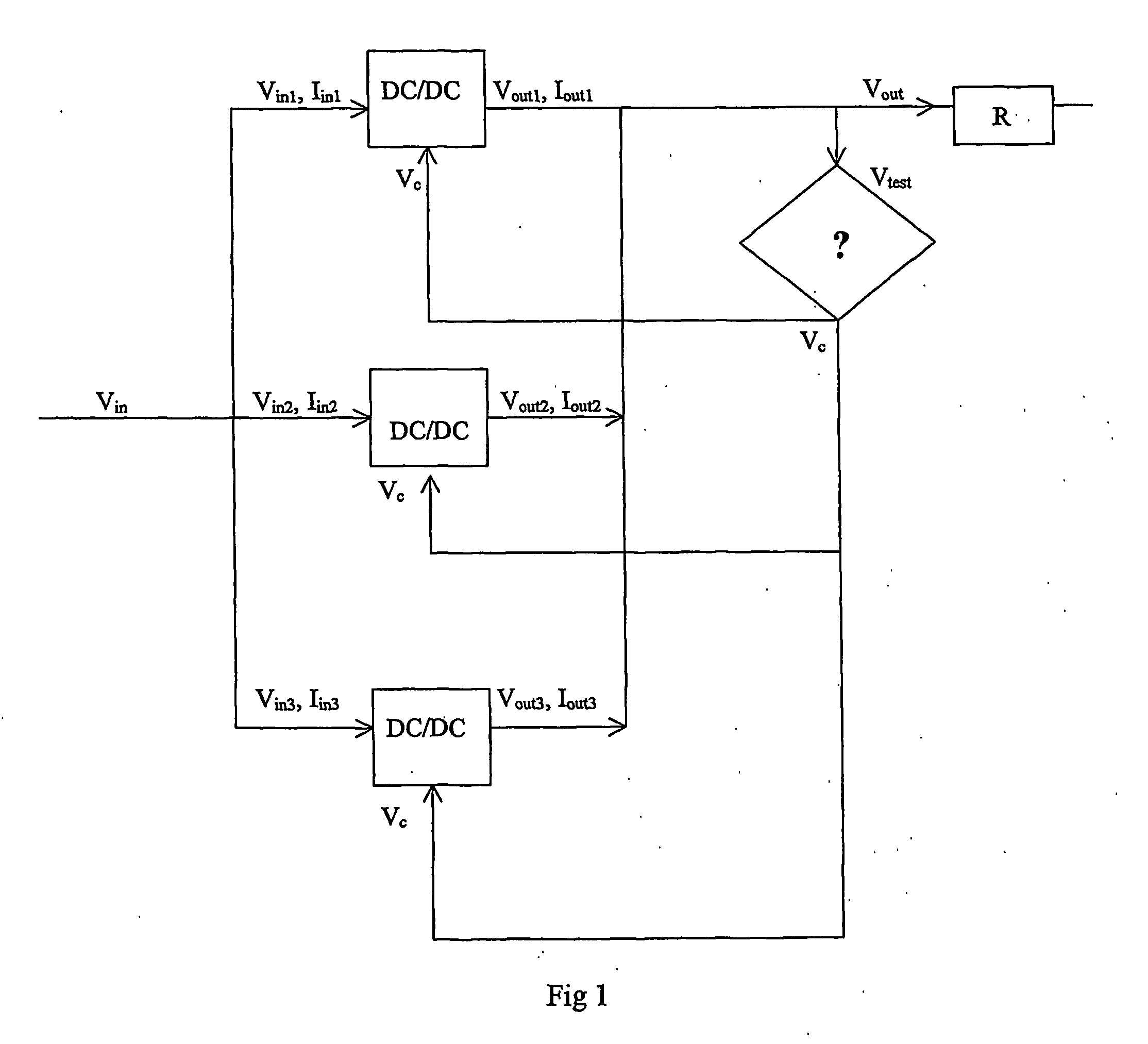
[0009] In FIG. 1, a schematic circuit diagram of a device 100 according to the invention is shown. The main purpose of the device 100 is to convert an input DC-voltage level, Vin, to an output DC-voltage level, Vout. The device 100 is intended to be mounted on a printed circuit board, a PCB, and to be small, inexpensive, and easy to assemble. As for the desire for the device to be small, this refers mainly to the “height” of the device, i.e. the physical dimension which extends “upwards” from the PCB.

[0010] In addition, there is a need for the device 100 to be able to handle rather large power levels. This need would normally be difficult to combine with the desire for a small device, since DC / DC-converters which can handle large power levels tend to be bulky, thus taking up large amounts of space, and which also leads to such devices being rather difficult to assemble on a standard assembly line.

[0011] These two contradictory desires, i.e. large power levels and small devices, is...


PUM


Abstract

The invention relates to a power device (100), comprising at least a first and a second DC-DC-converter (110, 120, 130), each converter having respective input and output voltages, and respective input and output currents, each converter (110, 120, 130) converting an input DC-voltage level to an output DC-voltage level, each converter comprising input means for a control signal (Vc), the device (100) additionally comprising a control means (140) common to the first and second converters, and arranged to detect a first output voltage (Vtest) at a point (150) in the device which is a common point for the output voltages of the first and second converter (110, 120, 130), the control means (140) delivering a common control signal (Vc) to the control input means of each converter, said common control signal (Vc) being varied according to the level of the voltage at said common point (150).

Description

TECHNICAL FIELD [0001] The present invention relates to a power device for conversion between different DC-voltage levels. BACKGROUND ART [0002] Devices for conversion between different DC / DC-voltage levels are well known. However, traditionally when there has been a need for a conversion involving rather high power levels, the tendency has been to use converters which are also larger physically. In applications where there is a desire for the converters to be small, for example when there is extremely limited space for the circuit boards on which the converters are mounted, the use of larger devices has proven impractical. DISCLOSURE OF THE INVENTION [0003] There is thus a need for a device which can convert a first DC-voltage level to a second DC-voltage level, with the device being able to handle rather high power levels, while at the same time occupying a minimal amount of space. In addition, the device should be capable of delivering a stable output voltage regardless of variat...

Claims


Application Information

Patent Timeline
IPC IPC(8): H02J1/10H02M3/156
CPCH02J1/102
Inventor DERMARK, DANIEL
Owner TELEFON AB LM ERICSSON (PUBL)
Why Eureka
Try Eureka