
System and method for controlling bidirectional three-phase DC/DC converter

a technology of dc/dc converter and system, which is applied in the direction of process and machine control, ignition automatic control, instruments, etc., can solve the problems of reducing the efficiency of dc/dc converter, and preventing traditional control methods such as gain control methods

Inactive Publication Date: 2006-06-29
HYUNDAI MOTOR CO LTD
View PDF2 Cites 12 Cited by
  • Summary
  • Abstract
  • Description
  • Claims
  • Application Information

AI Technical Summary

Benefits of technology

[0005] In some embodiments of the present invention, an apparatus for controlling a DC / DC converter, which controls energy flow between a first DC source and a second DC source, includes a voltage controller for calculating a current command value for the input current of the second DC source which is used to offset a difference between a voltage command value for the output voltage of the first DC source and the measured output voltage of the first DC source. One or more subtractors calculate differences between the current command value and the measured currents of respective phases of the DC / DC converter. One or more fundamental component current controllers calculate fundamental component control voltage command values of the respective phases of the DC / DC converter which are used to offset the differences between the current command values and currents of the respective phases. A first coordinate transformer transforms the calculated current differences into values in an orthogonal stationary coordinate system. A resonance current component extractor extracts resonance current components from the transformed values in the orthogonal stationary coordinate system. A resonance frequency tracker estimates resonance frequency variation from the extracted resonance current components and feeds back the estimated resonance frequency variation to the resonance current component extractor. One or more resonance component current controllers calculate voltage command values in the orthogonal stationary coordinate system, which are used to offset the extracted resonance current components. A second coordinate transformer calculate resonance component control voltage command values for the respective phases of the DC / DC converter by inversely transforming the calculated voltage command values in the orthogonal stationary coordinate system into coordinate systems corresponding to the respective phases of the DC / DC converter. One or more adders calculate final voltage command values by adding the fundamental component control voltage command values of the respective phases to respective resonance component control voltage command values. A Pulse Width Modulation (PWM) signal generation unit generates a PWM signal for controlling the DC / DC converter based on the final voltage command values.
[0006] In some other embodiments of the present invention, a method of controlling a DC / DC converter, which controls energy flow between a first DC source and a second DC source, includes the steps of calculating a current command value for the input current of the second DC source which is used to offset difference between a voltage command value for the output voltage of the first DC source and a measured output voltage of the first DC source; calculating differences between the current command value and the measured currents of respective phases of the DC / DC converter; calculating fundamental component control voltage command values of the respective phases of the DC / DC converter which are used to offset the differences between the current command values and currents of the respective phases; transforming the calculated differences into values in an orthogonal stationary coordinate system; extracting resonance current components from the transformed values in the orthogonal stationary coordinate system using a resonance current component extractor; estimating resonance frequency variation from the extracted resonance current components and feeding back the estimated resonance frequency variation to the resonance current component extractor; calculating voltage command values in the orthogonal stationary coordinate system, which are used to offset the extracted resonance current components; calculating resonance component control voltage command values for the respective phases of the DC / DC converter by inversely transforming the calculated voltage command values in the orthogonal stationary coordinate system into those coordinate systems corresponding to the respective phases of the DC / DC converter; calculating final voltage command values by adding the fundamental component control voltage command values of the respective phases to respective resonance component control voltage command values; and generating a PWM signal for controlling the DC / DC converter based on the final voltage command values.

Problems solved by technology

But small values of the corresponding inductance and capacitance for the filters may cause a high-frequency resonance generated between the inductors and the capacitors, which is difficult to prevent using traditional control methods such as a gain control method.
The high-frequency resonance results in a ripple generated in output power and voltage as well as heat generated at the inductors and the capacitors, thereby reducing the DC / DC converter's efficiency.

Method used


Image

  • System and method for controlling bidirectional three-phase DC/DC converter
  • System and method for controlling bidirectional three-phase DC/DC converter
  • System and method for controlling bidirectional three-phase DC/DC converter

Examples


Embodiment Construction

[0011] Embodiments of the present invention will be described below with reference to the accompanying drawings.

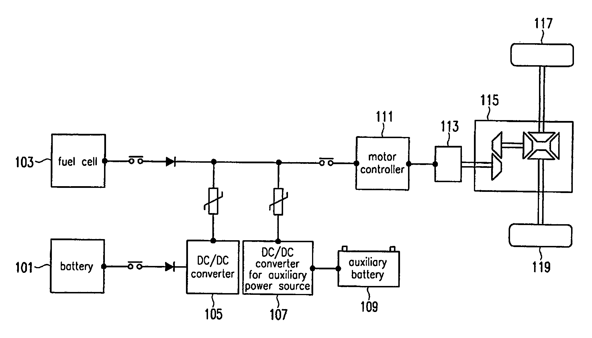
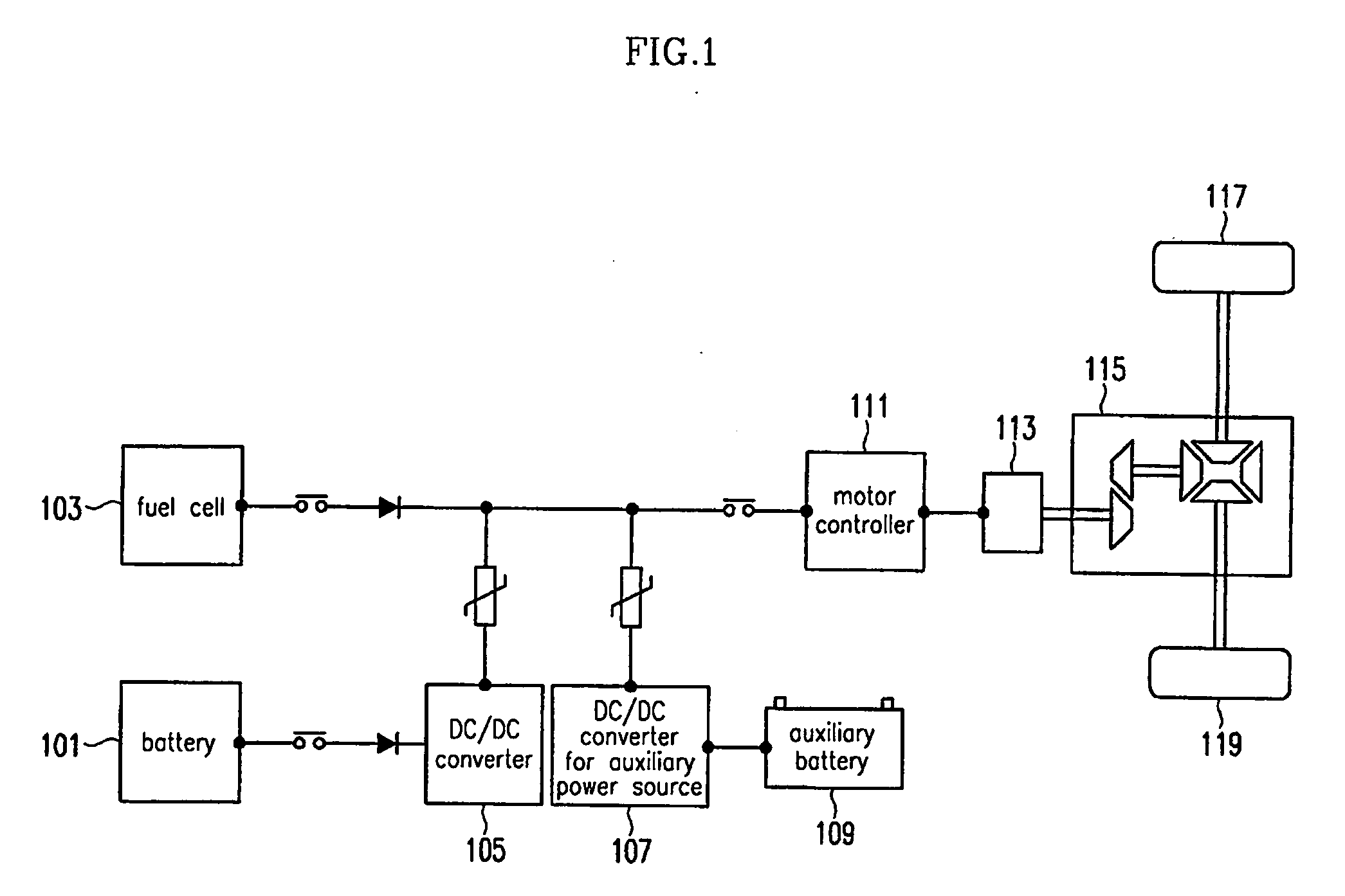
[0012] Referring to FIG. 1, a bi-directional three-phase DC / DC converter 105 is a component of the power system of a hybrid electric vehicle. The DC / DC converter 105 controls energy flow through DC-DC conversion between different DC sources like a battery 101 and a fuel cell 103. A motor controller 111 controls the operation of a motor 113 using the electric energy of the battery 101 or fuel cell 103. The power generated by the motor 113 passes through a decelerator 115 and is transferred to the wheels 117 and 119 of the vehicle. The power system of the hybrid electric vehicle may further include an auxiliary battery 109, and a DC / DC converter for an auxiliary power source 107, which controls the energy flow of the auxiliary battery 109.

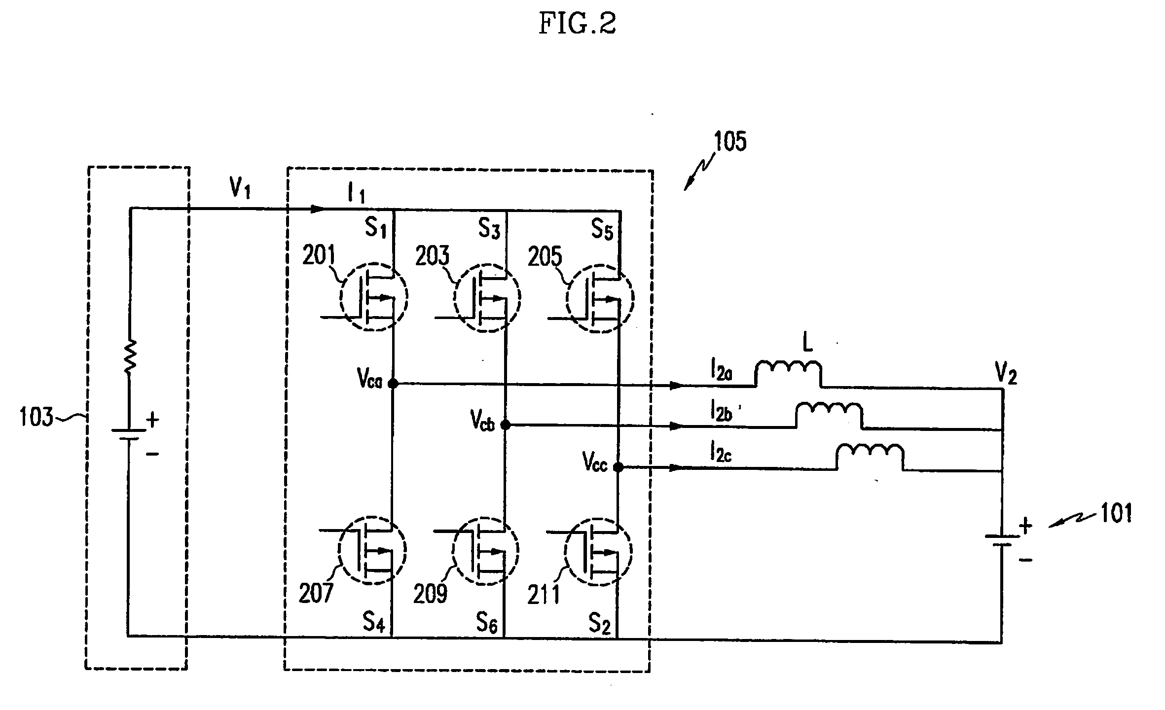
[0013] As shown in FIG. 2, the DC / DC converter 105 includes a plurality of switching devices 201, 203, 205, 207, 209 and 211 for perform...


PUM


Abstract

Disclosed are an apparatus and method for controlling a Direct Current (DC) / DC converter which controls energy flow between a first DC source and a second DC source to eliminate a high-frequency resonance. The apparatus for controlling the DC / DC converter includes a voltage controller, one or more subtractors, one or more fundamental component current controllers, a first coordinate transformer, a resonance current component extractor, a resonance frequency tracker, one or more resonance component current controllers, a second coordinate transformer, one or more adders and a Pulse Width Modulation (PWM) signal generation unit. The method implemented by the apparatus can effectively control any high-frequency resonance current components generated in the DC / DC converter.

Description

CROSS-REFERENCE TO RELATED APPLICATIONS [0001] The present application is based on, and claims priority from, Korean Application Serial Number 10-2004-0111260, filed on Dec. 23, 2004, the disclosure of which is hereby incorporated by reference herein in its entirety. FIELD OF THE INVENTION [0002] The present invention relates to an apparatus and method for controlling a Direct Current (DC) / DC converter. BACKGROUND OF THE INVENTION [0003] A multi-phase DC / DC converter is a device used in a hybrid electric vehicle or a fuel cell vehicle, etc. The DC / DC converter is responsible for transferring energy between different DC sources bi-directionally or uni-directionally under the control of voltage control logic. The voltage control logic, efficiency and weight of the DC / DC converter are directly related to the gas mileage of a vehicle having the DC / DC converter. Thus, the development of a highly efficient and low weight DC / DC converter is essential for the improvement of the gas mileage ...

Claims


Application Information

Patent Timeline
Patent Type & Authority Applications(United States)
IPC IPC(8): H02M7/00
CPCH02J7/34H02J2001/004H02M3/1584H02J2300/30H02M3/28
Inventor SONG, HONG-SEOK
Owner HYUNDAI MOTOR CO LTD
Learn More