
Unbalanced voltage compensation method, unbalanced voltage compensator, three-phase converter control method, and controller of three-phase converter

a three-phase converter and voltage compensation technology, applied in the direction of power oscillation reduction/prevention, ac-ac conversion, conversion with intermediate conversion to dc, etc., can solve the problem of inability to perform unbalanced voltage compensation

Active Publication Date: 2013-02-26
KYOSAN ELECTRIC MFG CO LTD
View PDF6 Cites 12 Cited by
  • Summary
  • Abstract
  • Description
  • Claims
  • Application Information

AI Technical Summary

Benefits of technology

[0101]As described above, according to each of the embodiments of the present invention; the unbalanced voltage compensation method, the unbalanced voltage compensator, the three-phase converter control method, the controller of the three-phase converter, and the unbalanced voltage compensation program, it is possible to derive from the line voltages, instantaneous values of the wye-phase voltages of wye-connection which are 120° out of phase with each other, in performing the unbalanced voltage compensation in the three-phase AC.
[0102]According to the present invention, in performing the unbalanced voltage compensation in the three-phase AC, it is possible to derive from actual values of the line voltages at one actual measurement point of time, being the three-phase unbalanced voltages, the positive-phase-sequence voltage, the negative-phase-sequence voltage, and the zero-phase-sequence voltage, which are the three-phase unbalanced voltages of wye-connection being 120° out of phase with each other at the time of the actual measurement.

Problems solved by technology

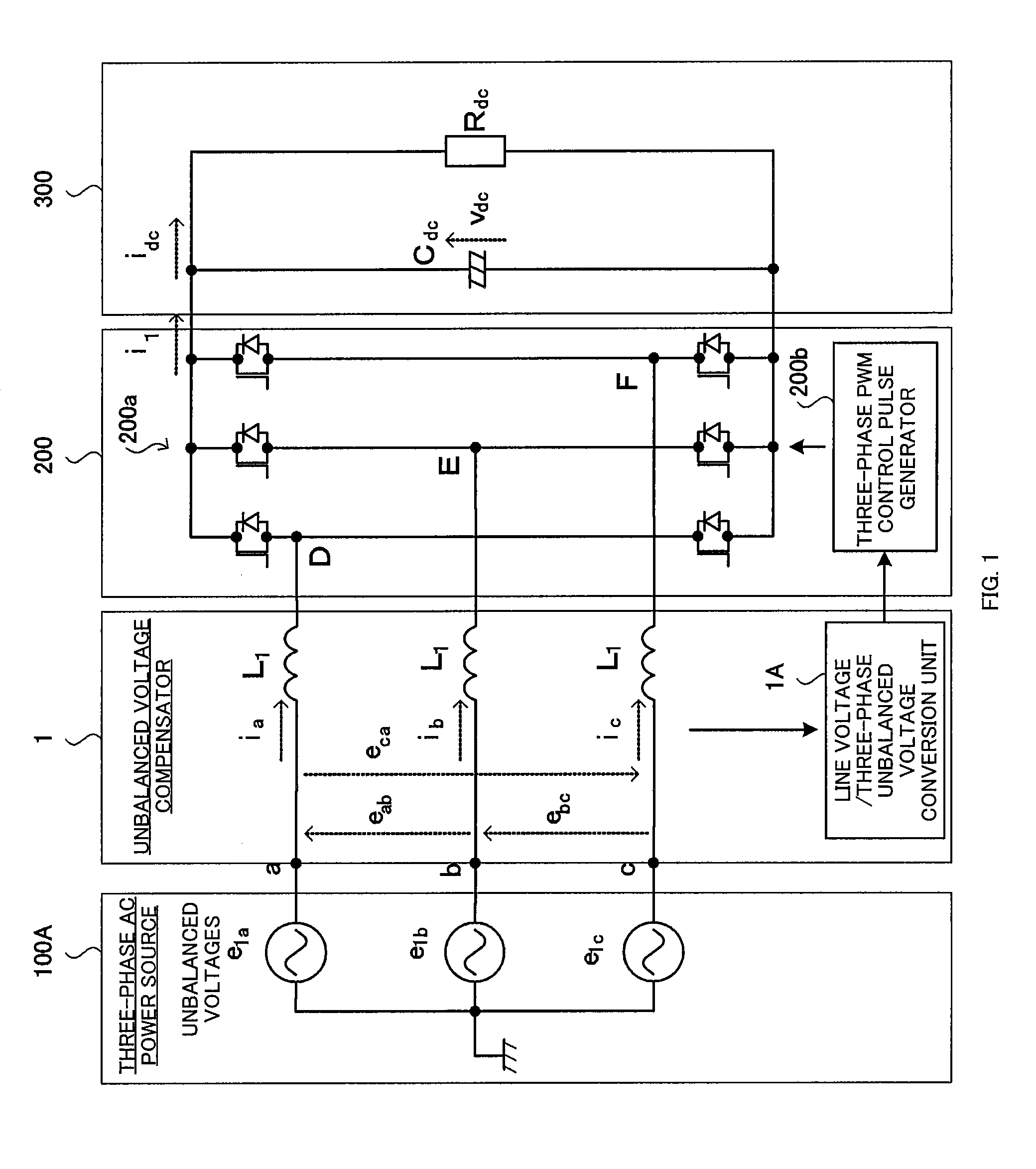
However, if these three-phase unbalanced voltages e1a, e1b, and e1c are unknown or unmeasurable, the unbalanced voltage compensation cannot be performed.

Method used


Image

  • Unbalanced voltage compensation method, unbalanced voltage compensator, three-phase converter control method, and controller of three-phase converter
  • Unbalanced voltage compensation method, unbalanced voltage compensator, three-phase converter control method, and controller of three-phase converter
  • Unbalanced voltage compensation method, unbalanced voltage compensator, three-phase converter control method, and controller of three-phase converter

Examples


Embodiment Construction

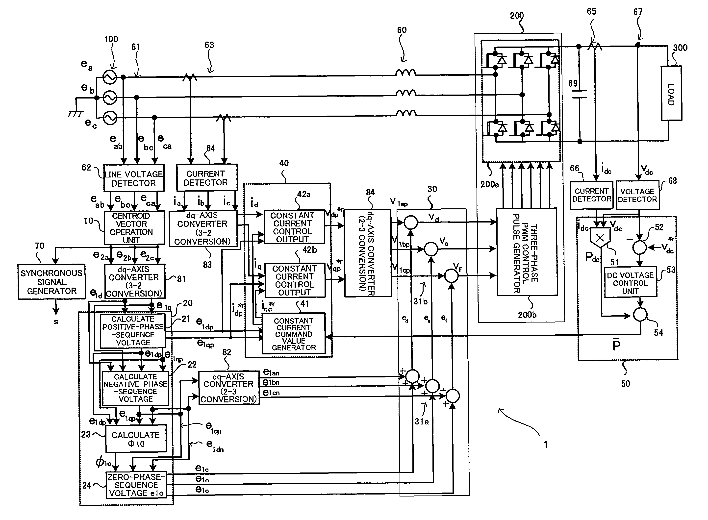
[0121]Hereinafter, preferred embodiments of the present invention will be explained in detail with reference to the accompanying drawings. With reference to FIG. 2 to FIG. 9, a configuration of the unbalanced voltage compensator of the present invention and an unbalanced voltage compensation method of the present invention will be explained, taking a three-phase converter as an example, and experimental results of the embodiments will be explained with reference to FIG. 10 to FIG. 15.

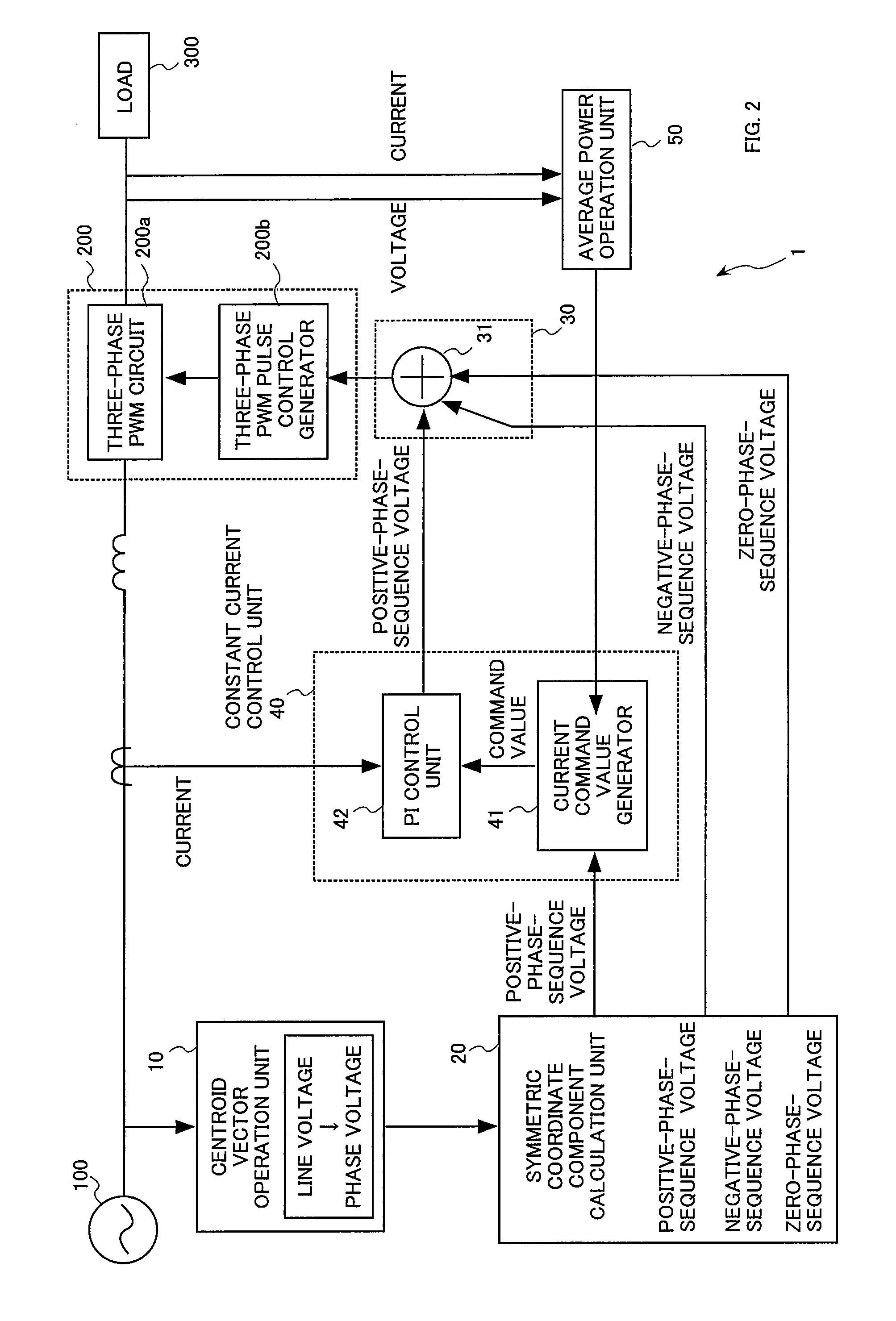
[0122]With reference to FIG. 2, a schematic configuration of the unbalanced voltage compensator of the present invention will be explained. In FIG. 2, a three-phase AC power source 100 supplies three-phase AC power, and the three-phase converter 200 subjects the three-phase AC power to the PWM conversion to output DC voltage to the DC load 300.

[0123]The unbalanced voltage compensator 1 of the present invention compensates for unbalanced voltages in the three-phase AC power, and suppresses fluctuations o...


PUM


Abstract

In compensating for unbalanced voltages of three-phase AC, instantaneous values of wye-phase voltages 120° out of phase with each other are obtained from line voltages using a centroid vector operation, symmetrical component voltages of three-phase balanced system are obtained from the instantaneous values of wye-phase voltages, a compensation signal to compensate unbalanced voltages of three-phase AC is generated from zero-phase-sequence voltage of symmetrical component voltages is generated, wye-phase voltages 120° out of phase, the unbalanced voltages of which are compensated, are obtained from the compensation signal and the symmetrical component voltages, a control signal of a PWM conversion is generated based on the compensated wye-phase voltage compensated, and the unbalanced voltages of three-phase AC are compensated. The amount of time to compensate the three-phase unbalanced voltages required for detecting an unbalance of voltages and generating a control signal can be shortened.

Description

BACKGROUND OF THE INVENTION[0001]1. Field of the Invention[0002]The present invention relates to unbalanced voltage compensation, and more particularly, it relates to a method and a compensator for compensating for unbalance of three-phase AC (alternating current), and a control method and a controller for compensating for the unbalance of three-phase AC in a three-phase converter which converts three-phase AC power into DC (direct current) power.[0003]2. Description of the Related Art[0004]It is known that occurrence of voltage reduction on the power source side, such as instantaneous voltage drop (voltage sag) and a long-term voltage reduction, has an impact on the load side which receives power supply from the power source, such as production line stop and defects in manufactured goods. In particular, since it has a significant impact on semiconductor manufacturing equipment, standards are established regarding the voltage sag; “SEMI F47-0200” (non-patent document 1), and “SEMI F...

Claims


Application Information

Patent Timeline
Patent Type & Authority Patents(United States)
IPC IPC(8): H02M7/217
CPCH02M7/219H02M2001/0022H02M1/0022
Inventor YUZURIHARA, ITSUOTAKAYANAGI, ATSUSHIHATA, YOSHIHISA
Owner KYOSAN ELECTRIC MFG CO LTD
Learn More