
Storage apparatus

a technology for storage apparatuses and storage devices, applied in the field of storage apparatuses, can solve the problems of limited data input/output between the first storage apparatus and the other apparatus such as the information processor or the second storage apparatus, and achieve the effect of reducing the load from saving/recovering and improving the performance of data input/outpu

Active Publication Date: 2006-06-29
HITACHI LTD
View PDF10 Cites 10 Cited by
  • Summary
  • Abstract
  • Description
  • Claims
  • Application Information

AI Technical Summary

Benefits of technology

[0006] The present invention is made in light of the problem stated above, and its object is to provide a technique for using, when the data input / output is executed between the storage apparatus and the other apparatus, inter-memory data transfer information or data save / recover operations to perform the multiprocessing of the data transfer with other apparatus by the data transfer control unit of the controller and further for improving the performance of the data input / output by suppressing loads caused due to the above save / recover operations.
[0022] Effects obtained from representative ones of the inventions disclosed in the present application will be briefly described as follows. According to the present invention, when the data input / output is executed between the storage apparatus and the other apparatus, the data transfer controller of the controller uses the saving / recovering operation to the data transfer information and the data between the memories to multiprocess the data transfer between the other apparatus and the storage apparatus, and further suppresses the load from the saving / recovery, so that the performance of the data input / output can be improved.

Problems solved by technology

In the operation, however, performance of data input / output between the first storage apparatus and the other apparatus such as the information processor or second storage apparatus is limited by communication to be established with the other apparatuses.

Method used


Image

  • Storage apparatus
  • Storage apparatus
  • Storage apparatus

Examples


first embodiment

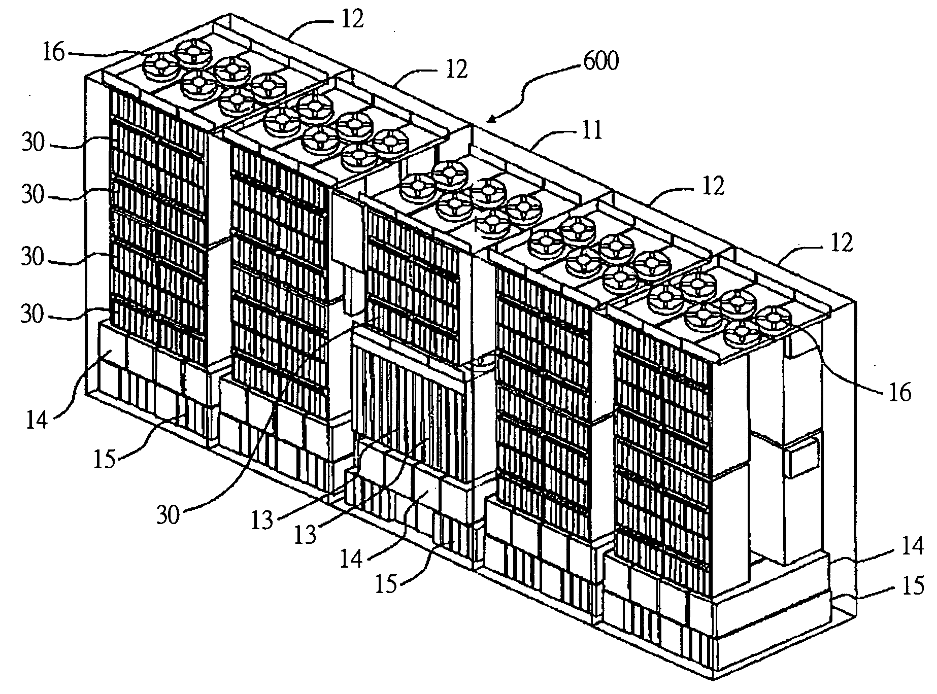
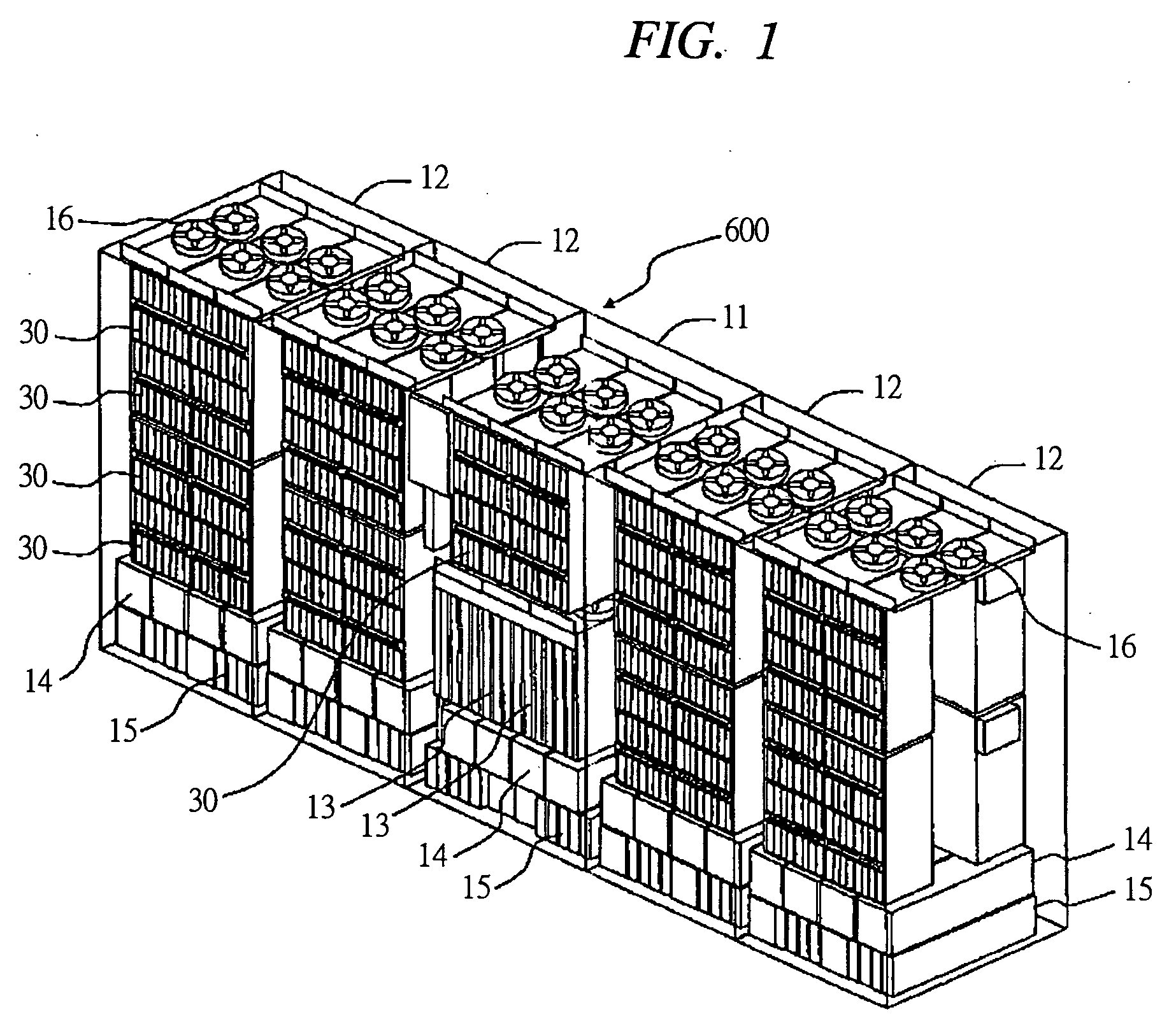
[0215] Next, the storage apparatus 600, which is a first embodiment, will be described. The basic operation represents control for performing the saving and recovering operations of the data transfer information and the data whenever the data transfer is executed. However, if the saving and recovery are executed often, loads due to executions of them are increased. In the storage apparatus 600 of each embodiment, the basic operations can be performed and concurrently it is possible to efficiently use the memory of the DMA unit 800 by the data transfer LSI 114 and control the data transfers in which the loads required for the saving and recovery are reduced by controlling the timing of the saving and recovering operations. In addition, a number of control methods can be selectively executed depending on the conditions. The first to fourth control in which the loads involved in the saving and recovery are reduced will be described below.

[0216] First, the storage apparatus of the firs...

second embodiment

[0237] Next, a description will be made of the storage apparatus 600 of a second embodiment. The storage apparatus 600 in the second embodiment exercises the second control for transferring the data.

[0238]

[0239] As the second control, a description will be made of the data transfer control for performing recovery reduction. As the second control, the data transfer LSI 114 exercises the control for reducing the recovering operation by utilizing the data transfer information and the data remaining in the memory of the DMA units 800. In other words, in a certain DMA unit 800, when the second data transfer is related to the first data transfer after executing the first data transfer and the saving, that is, when the data transfer information and the data necessary for the second data transfer remain in the register 807 and the buffer 810 of the DMA units 800, the second data transfer is executed by omitting the recovering operations. Thereby, the time required from the start to the end...

third embodiment

[0254] Next, a storage apparatus 600 of a third embodiment will be described. The storage apparatus 600 in the third embodiment executes the third control for transferring the data.

[0255]

[0256] As the third control, a description will be made of data transfer control for reducing the saving / recovering operations at the cache write. As the third control, in executing the data transfers by the DMA units 800, that is, when the plurality of pieces of data are transmitted to the CM 130 from the memory #2 (113) and the writing processing is performed, the data transfer LSI 114 writes (flushes) the transfer data from the buffer 810 to the CM 130 without executing the saving and recovery to the memory #3 (115) in each of the data transfers. Thereby, the saving and recovering operations are reduced. Due to the data transfer in one of the DMA units 800 in the data transfer LSI 114, the other of the DMA units 800 flushes the data from the buffer 810 to the CM 130.

[0257]FIGS. 18A and 18B show...


PUM


Abstract

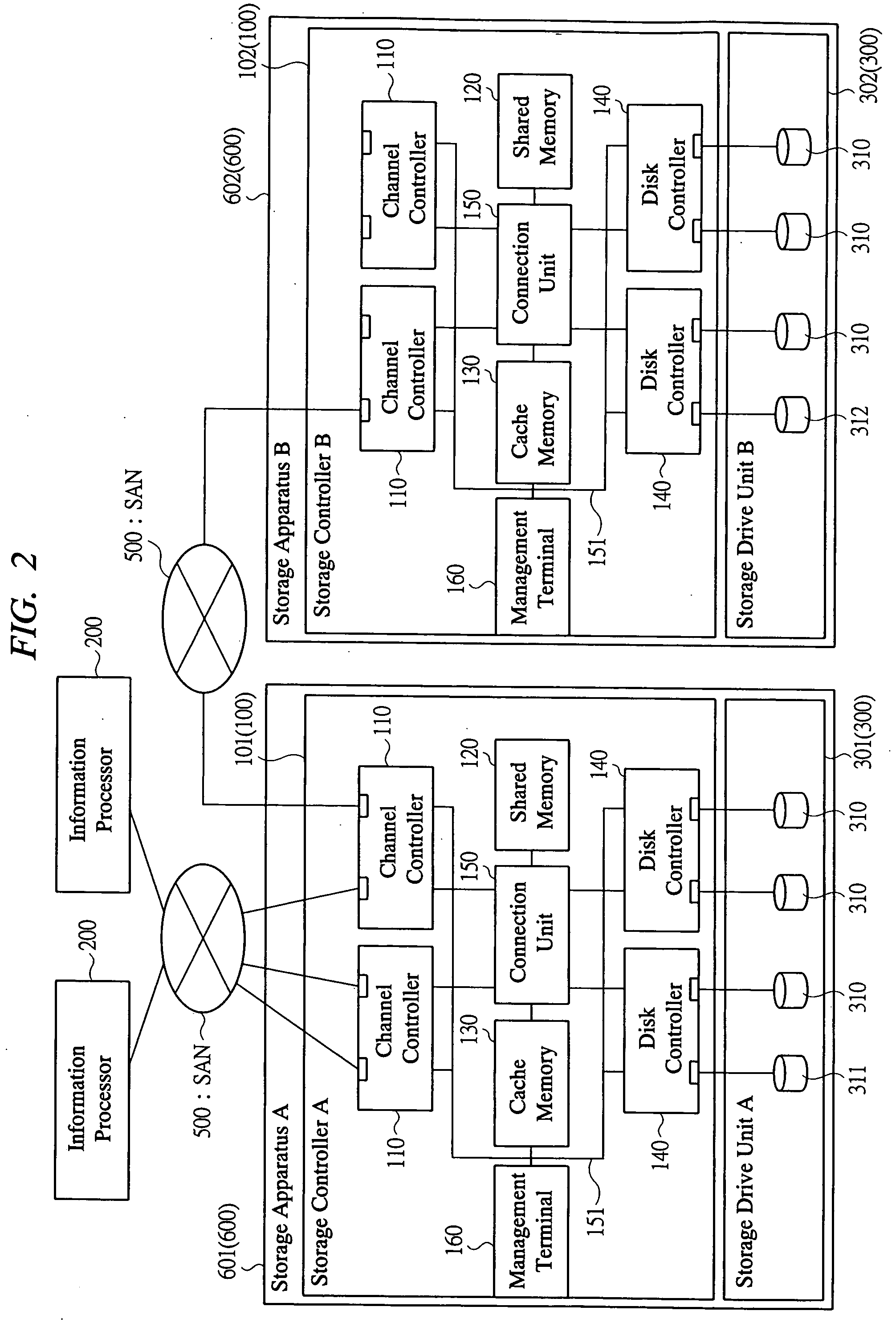
In a data input / output with other apparatus, a data transfer controller (DTC) of a storage controller multiprocesses a data transfer with the other apparatus by utilizing a saving / recovering operation and suppresses a load therefrom, thereby improving performance thereof. A first storage apparatus includes two DMA units in a data transfer LSI of the DTC, uses them to process one or more data transfer concurrently, uses the saving or recovering operation to a memory #3 also in one DMA unit to process the data transfer while the data transfers are switched, thereby multiprocessing a plurality of data transfers. Based on an instruction from the IOC, the DTC makes one of the DMA units recover the necessary data transfer information and data from the memory #3 and transfer the data to the memory, and concurrently the other of the DMA units, which is not processed presently, save in advance, to the memory #3, the data transfer information and the data stored in the memory.

Description

CROSS-REFERENCE TO RELATED APPLICATION [0001] The present application claims priority from Japanese patent application No. JP 2004-375453 filed on Dec. 27, 2004, the content of which is hereby incorporated by reference into this application. BACKGROUND OF THE INVENTION [0002] The present invention relates to a storage apparatus (also referred to as a disk array apparatus), and, more specifically, to a technique for controlling data transfer with an information processor to be a host or with any other apparatus such as other storage apparatus. [0003] Recently, in a technique of a storage apparatus, that is, in a configuration for communicatively connecting a plurality of storage apparatuses, a first storage apparatus receiving a data input / output request from an information processor is operated so as to access data stored in a second other storage apparatus connected communicably thereto. An example of such an operation includes a remote copy function between the storage apparatuses...

Claims


Application Information

Patent Timeline
Patent Type & Authority Applications(United States)
IPC IPC(8): G11C11/34
CPCG06F3/0613G06F3/0647G06F3/0656G06F3/0658G06F3/067
Inventor HIRAKO, NORIOKATO, SHOJI
Owner HITACHI LTD
Learn More