Piezoelectric panel speaker

Inactive Publication Date: 2006-06-29
CITIZEN ELECTRONICS CO LTD
View PDF13 Cites 45 Cited by
  • Summary
  • Abstract
  • Description
  • Claims
  • Application Information

AI Technical Summary

Benefits of technology

[0012] The present invention was made in view of the above-described circumstances. Accordingly, an object of the pre

Problems solved by technology

With the above-described structure, the panel speaker has difficulty in obtaining a favorably flat frequency characteristic curve and hence suffers from inferior ac

Method used


Image

  • Piezoelectric panel speaker
  • Piezoelectric panel speaker
  • Piezoelectric panel speaker

Examples


first embodiment

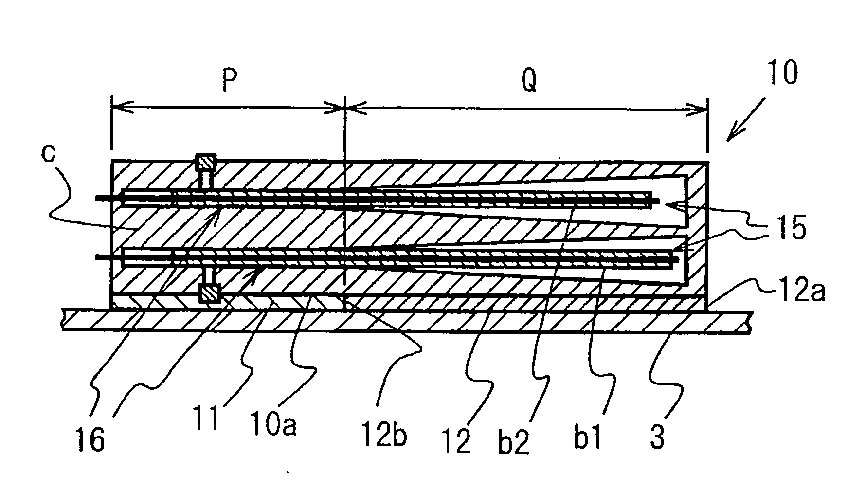
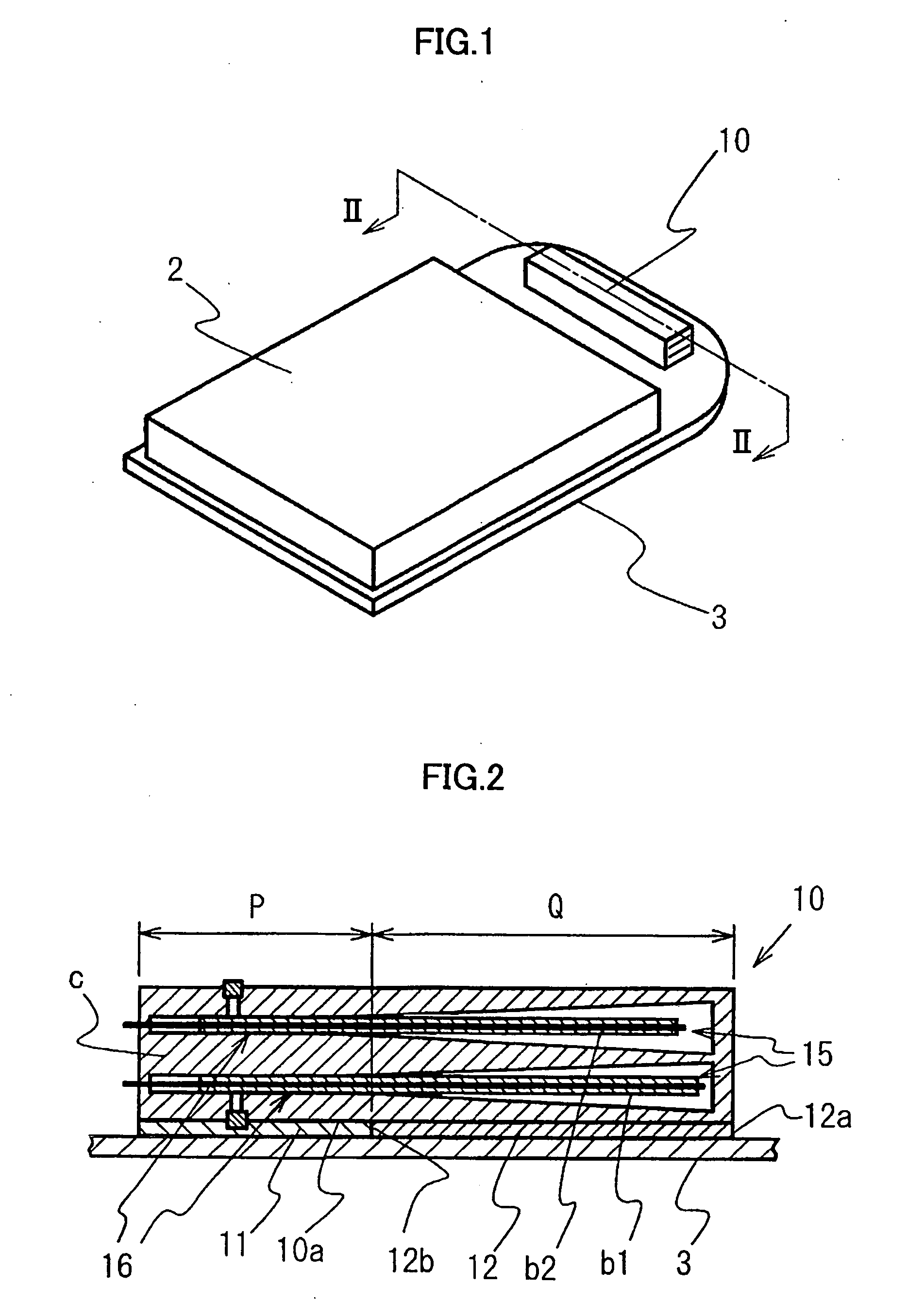
[0037]FIG. 1 shows a panel speaker according to the present invention. The panel speaker includes, as in the panel speaker explained above with reference to FIG. 9, a vibration panel 3, a liquid crystal panel 2 connected thereto through a soft spongy material (not shown) or the like and a piezoelectric exciter 10 secured to the vibration panel 3. The piezoelectric exciter 10 has two exciter elements b1 and b2 accommodated in a rectangular casing c. The casing c and the vibration panel may be made from acrylic resin. The piezoelectric exciter 10 has substantially the same arrangement as that of the piezoelectric exciter explained above with reference to FIG. 8. Therefore, a detailed description thereof is omitted.

[0038] As shown in FIG. 2, the piezoelectric exciter 10 is divided into a first region P and a second region Q. In the first region P, one end portion 16 of each of the exciter elements b1 and b2 is secured to the casing c. In the second region Q, the exciter elements b1 and...

second embodiment

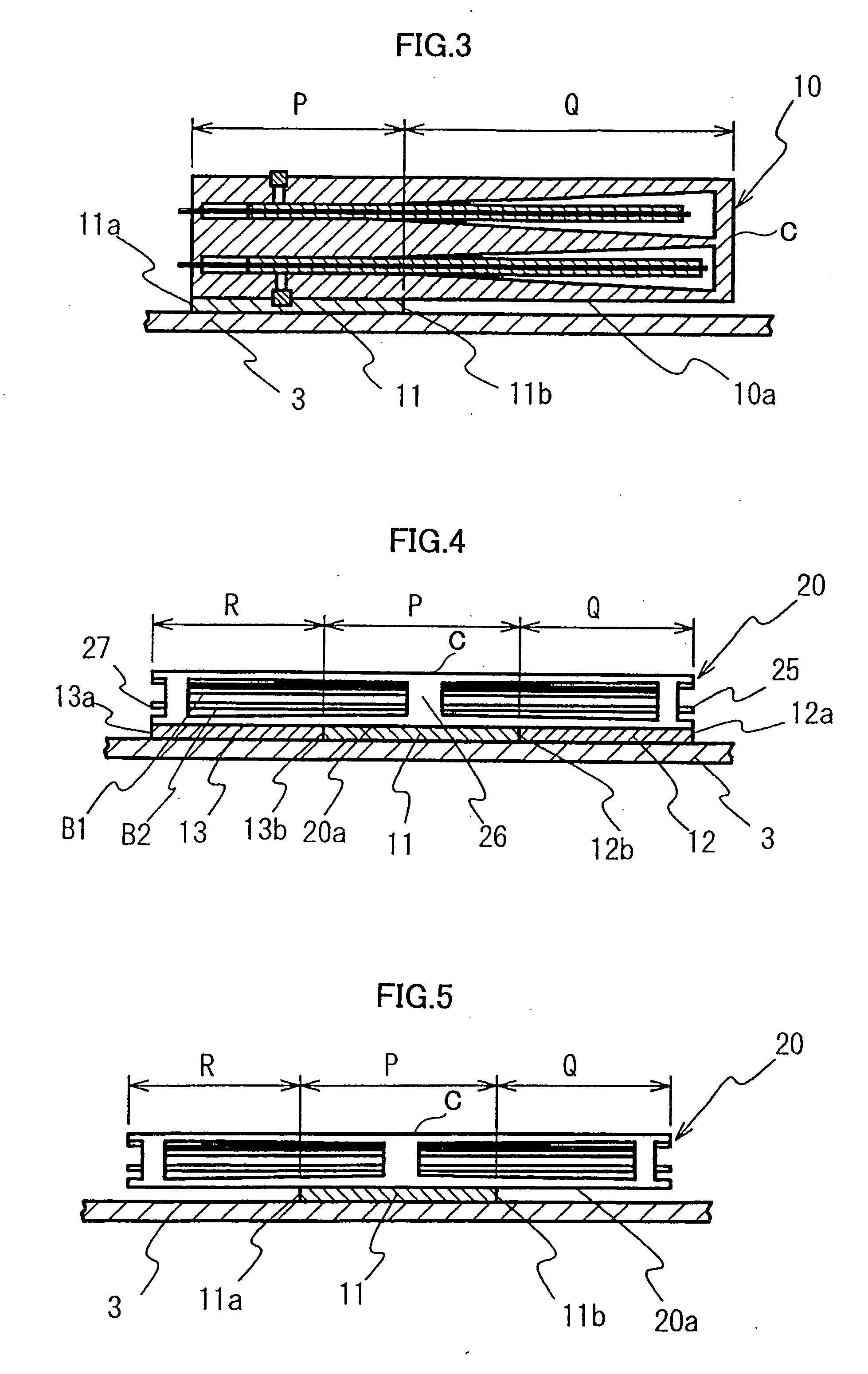
[0045]FIG. 3 illustrates the present invention, which is a modification of the panel speaker shown in FIG. 2. In the panel speaker shown in FIG. 3, the first region P of the lower surface 10a of the piezoelectric exciter 10 is secured to the vibration panel 3 with double-sided adhesive tape 11 having high elasticity. At the second region Q, a space is provided between the piezoelectric exciter 10 and the vibration panel 3. In this case also, the acoustic characteristics of the panel speaker change in relation to the dimension of the high-elasticity double-sided adhesive tape 11 from its one end 11a to the other end 11b. Therefore, the acoustic characteristics can be adjusted by changing the length of the double-sided adhesive tape 11.

third embodiment

[0046]FIG. 4 is a sectional view of a panel speaker according to the present invention. The panel speaker uses a piezoelectric exciter 20 having the same arrangement as that of the piezoelectric exciter explained above with reference to FIG. 10. That is, the piezoelectric exciter 20 has a retainer portion 26 formed in a central region of the casing to retain the respective central portions of the exciter elements or beams B1 and B2. The exciter elements extend to the right and left free ends 25 and 27 thereof.

[0047] In the piezoelectric exciter 20, the casing is divided into a central first region P where the exciter elements B1 and B2 are securely held and second regions Q and R on the right and left sides of the first region P.

[0048] At the first region P, the casing is secured to the vibration panel 3 with a securing member 11 having high elasticity in the same way as in the first embodiment. At the right and left second regions Q and R, cushiony or yieldable inserts 12 and 13 a...


PUM


Abstract

A piezoelectric panel speaker improved in frequency characteristics has a panel and a piezoelectric exciter for vibrating the panel. The exciter includes a casing and a piezoelectric exciter element accommodated in the casing. The casing has an outer surface with a part positioned proximate to and facing one side surface of the panel. The side surface of the panel has an area opposed to the part of the outer surface of the exciter. A securing layer is partially formed between the area of the panel and the part of the outer surface to secure the exciter to the panel. The securing layer is made of a material so that vibration is transmittable from the exciter to the panel.

Description

[0001] This application claims priority under 35 U.S.C. §119 to Japanese Patent Application No. 2004-377897 filed Dec. 27, 2004, the entire content of which is hereby incorporated by reference. BACKGROUND OF THE INVENTION [0002] 1. Field of the Invention [0003] The present invention relates to panel speakers and, more particularly, to a panel speaker using a piezoelectric exciter. [0004] 2. Description of the Background Art [0005] A panel speaker is a thin loudspeaker including a panel diaphragm (vibration panel) and an exciter that vibrates the diaphragm to generate sound. The panel speaker is used, for example, in cellular phones [see Japanese Patent Application Publication (KOKAI) No. 2004-336403]. FIG. 7 is a plan view showing the arrangement of the display part of such a cellular phone. The display part of the cellular phone has a liquid crystal panel 2 set in a casing 1, a speaker vibration panel 3 also serving as a light-transmitting protection panel that is set to close a di...

Claims


Application Information

Patent Timeline
IPC IPC(8): H04R25/00
CPCH04R7/045H04R17/00H04R2499/11H04R7/04
Inventor KOBAYASHI, KAZUHIRO
Owner CITIZEN ELECTRONICS CO LTD
Why Eureka
Try Eureka