
Image processing apparatus

a technology of image processing and apparatus, applied in the direction of instruments, color/spectral property measurement, material analysis, etc., can solve the problems of inability to obtain the fluorescence image of the cell, and the inability to recall the observation in which the same cell is again observed,

Inactive Publication Date: 2006-06-29
OLYMPUS CORP
View PDF13 Cites 8 Cited by
  • Summary
  • Abstract
  • Description
  • Claims
  • Application Information

AI Technical Summary

Problems solved by technology

So this technique has disadvantages that it cannot obtain the fluorescence image of the cell and a recall observation in which the same cell is again observed cannot be performed.

Method used


Image

  • Image processing apparatus
  • Image processing apparatus
  • Image processing apparatus

Examples


Embodiment Construction

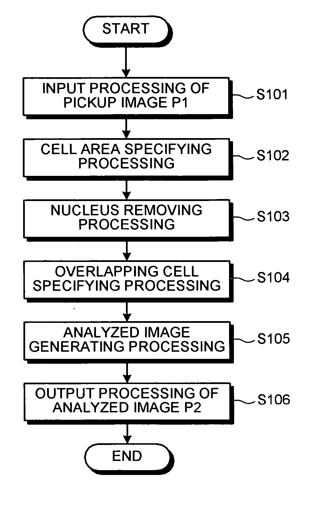
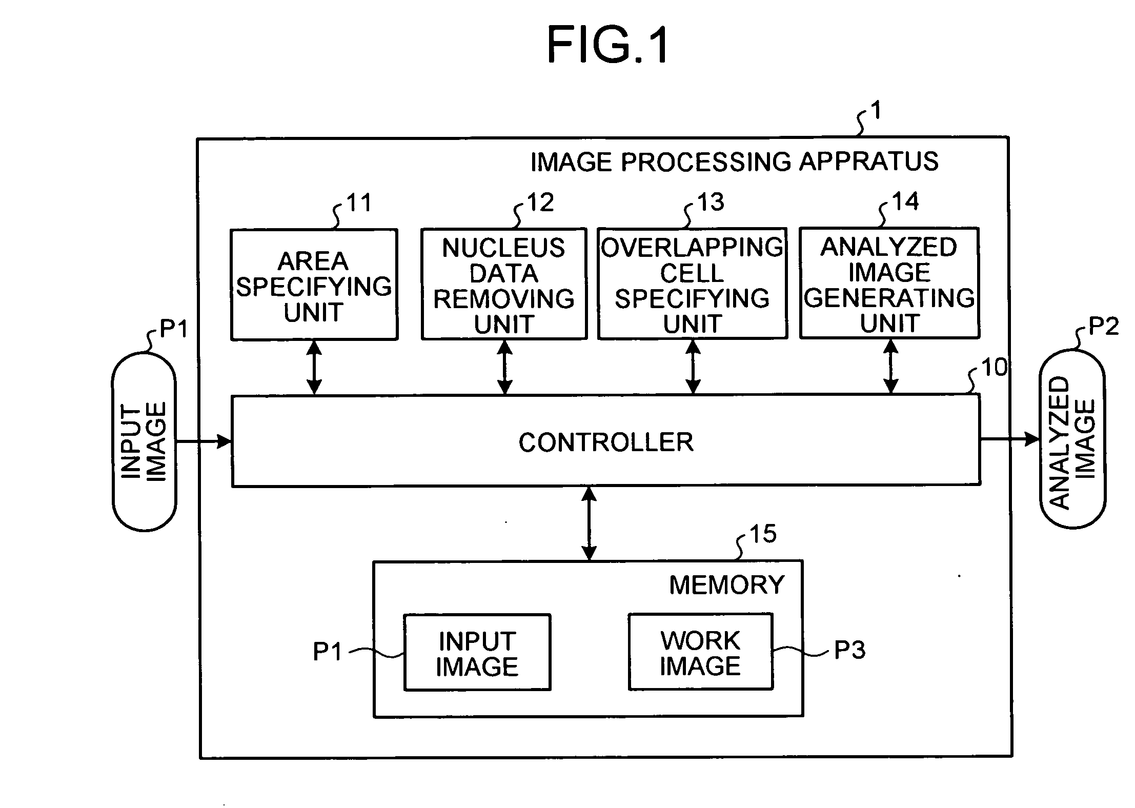
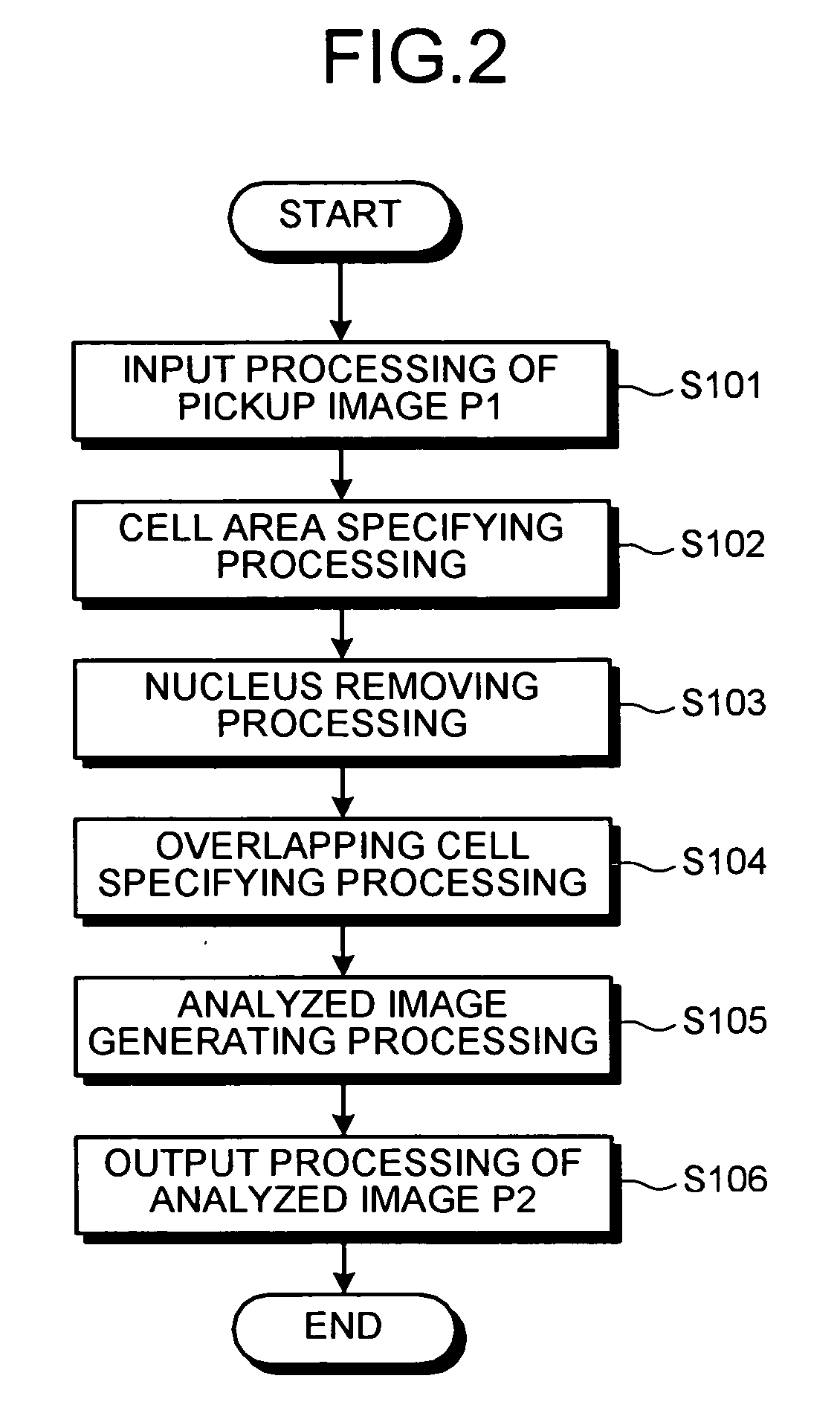
[0019]FIG. 1 is a block diagram showing the schematic structure of an image processing apparatus according to a first embodiment of the present invention. The image processing apparatus 1 is configured to accept an input image P1 obtained as a fluorescence image and then to output an analyzed image P2 in which image data of an overlapping cell is removed not to be analyzed.

[0020] The image processing apparatus 1, as shown in FIG. 1, includes a controller 10, an area specifying unit 11 that specifies a distribution area of the cells to be picked up, a nucleus data removing unit 12 that removes image data of a nucleus, an overlapping cell specifying unit 13 that specifies an overlapping cell, an analyzed image generating unit 14 that generates an analyzed image, and a memory 15 that stores the input image P1 and a work image P3. The controller 10 is connected to the area specifying unit 11, the nucleus data removing unit 12, the overlapping cell specifying unit 13, the analyzed image...


PUM


Abstract

An image processing apparatus includes an area specifying unit that specifies a closed area emitting fluorescence in a fluorescence image as a cell area in a cell population including a number of dispersed cells. The fluorescence image is generated from fluorescence emitted by the cell population irradiated with a scanning laser beam. The apparatus also includes a nucleus data removing unit that removes data corresponding to a nucleus in the cell area; an overlapping cell specifying unit that specifies an overlapping cell area where cells overlap, based on a fluorescence intensity of a cytoplasm portion corresponding to an image where the data corresponding to the nucleus is removed; and an analyzed image generating unit that generates an analyzed image where data of the overlapping cell area is removed from the fluorescence image.

Description

CROSS-REFERENCE TO RELATED APPLICATIONS [0001] This application is based upon and claims the benefit of priority from Japanese Patent Application No. 2004-381511, filed Dec. 28, 2004, the entire contents of which are incorporated herein by reference. BACKGROUND OF THE INVENTION [0002] 1. Field of the Invention [0003] The present invention relates to an image processing apparatus which is used in a scanning cytometer. The scanning cytometer irradiates a cell population including a number of dispersed cells with a scanning laser beam, and performs an image processing on a fluorescence image obtained based on fluorescence emitted by the cell population, thereby analyzing the cells in the image. [0004] 2. Description of the Related Art [0005] Conventionally, a cytometry has been widely used to investigate a transition process of a cancer cell and the like. In the cytometry technique, a laser beam irradiates a cell population including a number of dispersed cells so that a fluorescence i...

Claims


Application Information

Patent Timeline
Patent Type & Authority Applications(United States)
IPC IPC(8): G06K9/00
CPCG06K9/00127G06V20/69
Inventor AOKI, MASAHIRO
Owner OLYMPUS CORP
Learn More