

Reflection optical system and projection display apparatus using the same
- Summary
- Abstract
- Description
- Claims
- Application Information
AI Technical Summary
Benefits of technology
Problems solved by technology
Method used
Image

Examples
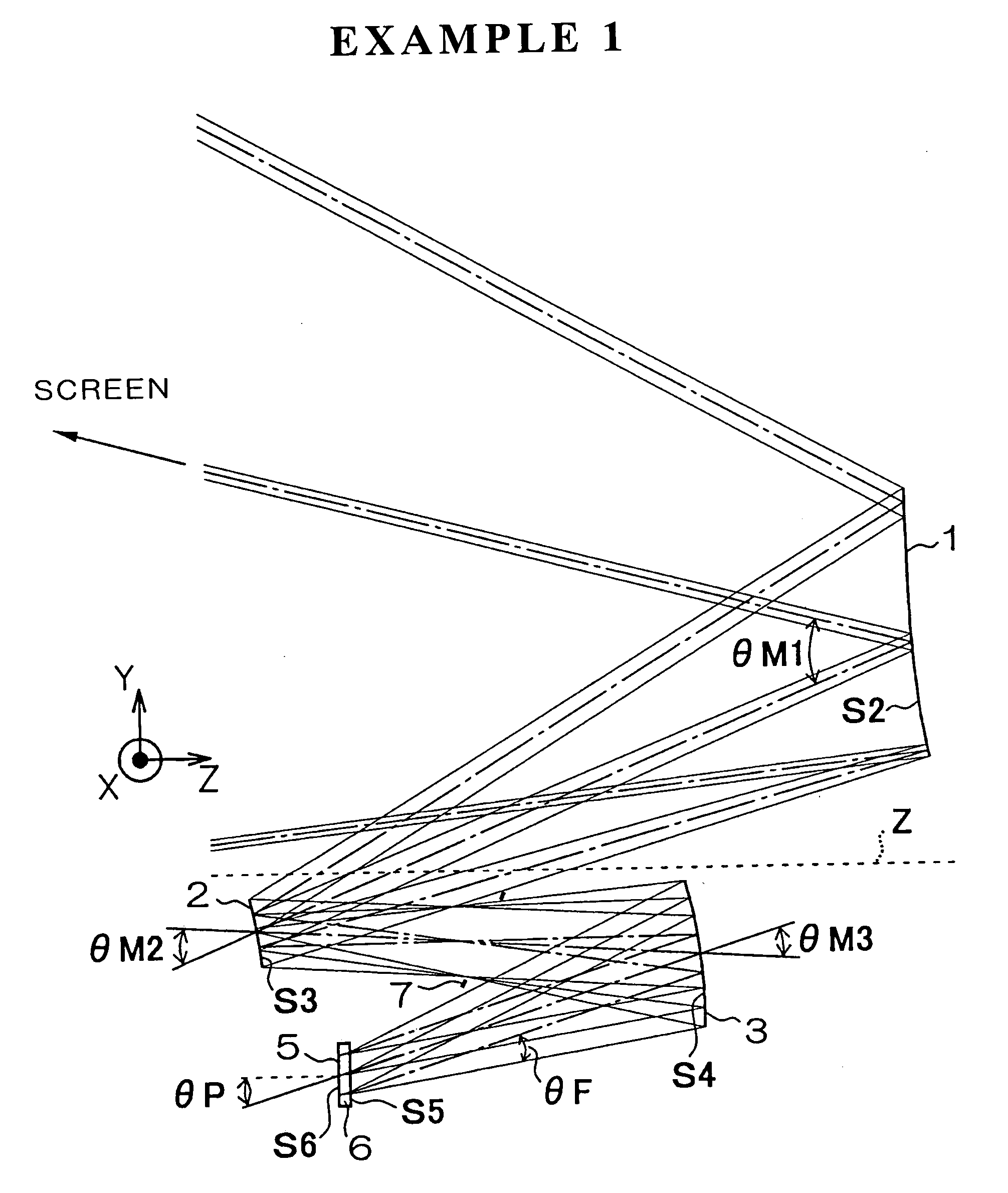
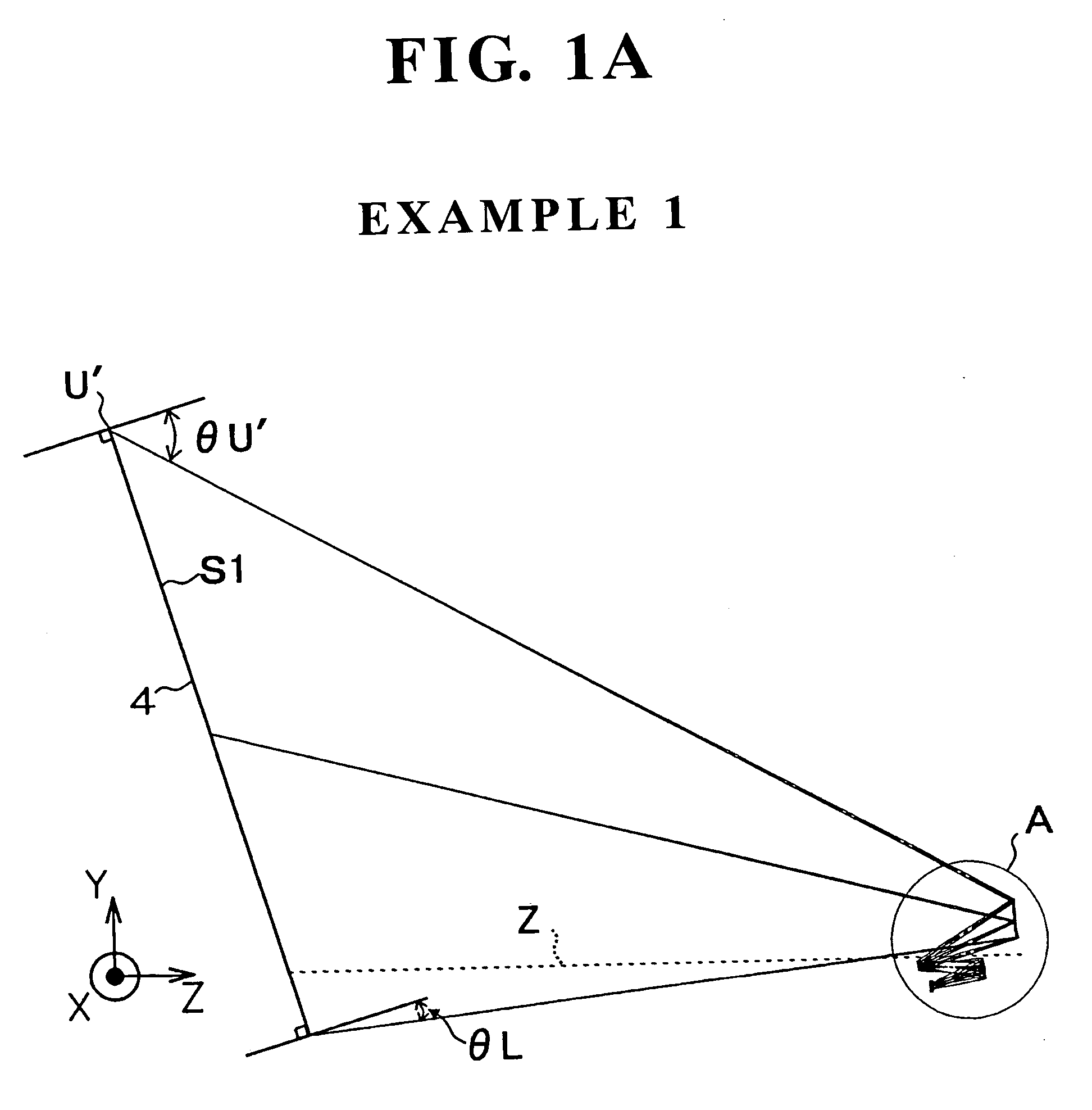
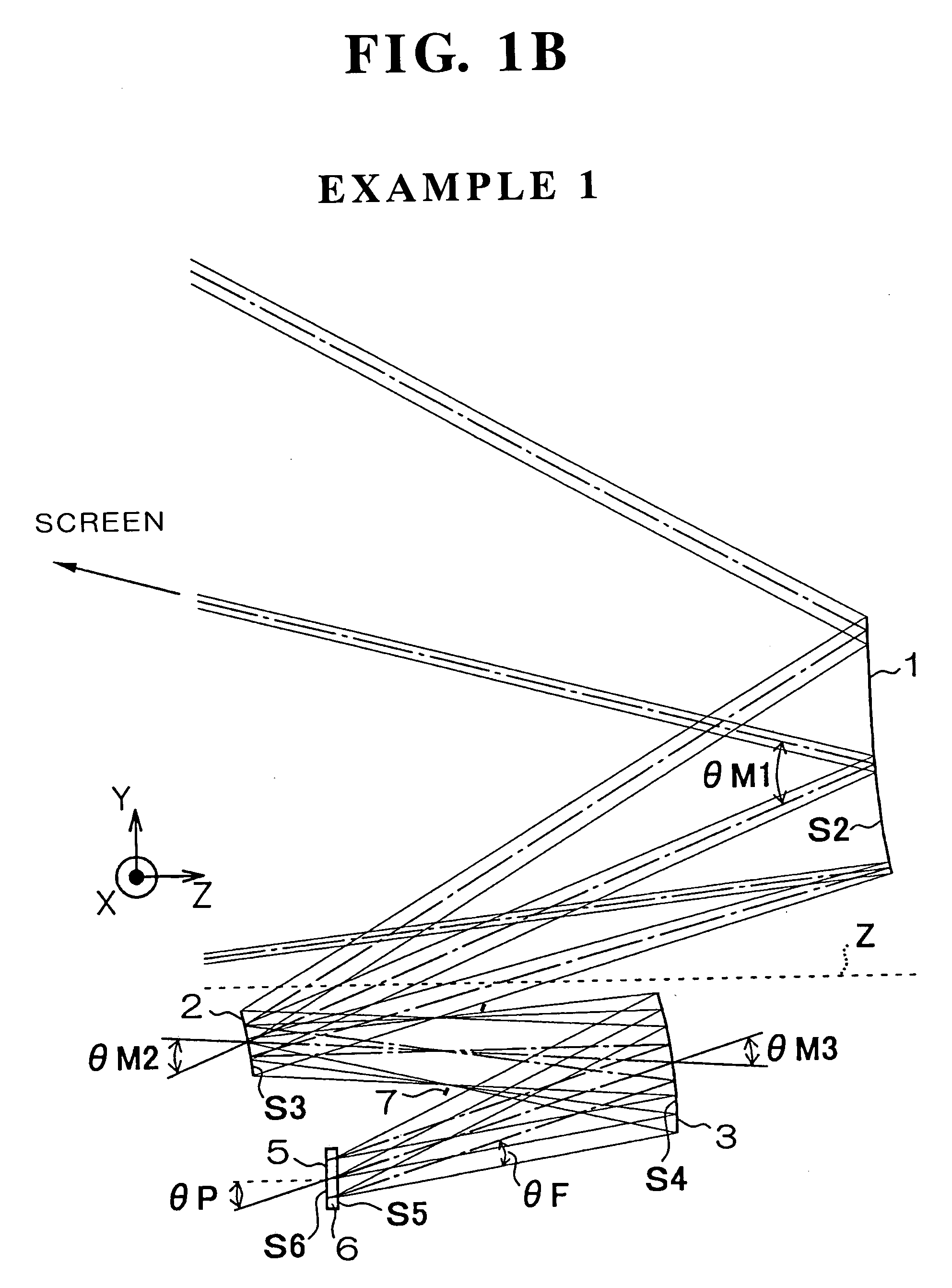
example 1
[0196]
TABLE 1-1SurfacenumberRadius of curvatureDistance in Z directionNdνd*S1∞92.9241*S222.2831−13.1522(mirror)*S3−11.51437.9270(mirror)*S4−8.8939−6.2930(mirror) S5∞−0.21421.4874970.2*S6∞
*Eccentric surface
[0197]
TABLE 1-2Eccentricity dataSurface numberShift in Y directionRotation about X axisS10.000016.7014S20.4577−8.0644S3−1.58912.4355S40.21123.1507S6−3.83620.0000
[0198]
TABLE 1-3Surface numberDistance in Z directionShift in Y directionFocus 1S159.73630.0000S2−13.41170.4453Focus 2S1192.51890.0000S2−12.88040.4707
[0199]
TABLE 1-4Reduction side pupil position∞Reduction side pupil central angle17.651Reduction side pupil divergent angle±8.213
[0200]
TABLE 1-5Reduction side effective areaX direction±0.50000Y direction±0.37500
[0201]
TABLE 2 Aspherical dataSurface number S2K1.00001C(1, 0)C(0, 1)C(2, 0)C(1, 1)C(0, 2)C(3, 0)C(2, 1)C(1, 2)C(0, 3)C(4, 0) A4−1.20796 × 10−40.00000−5.17458 × 10−11.53943 × 10−20.000004.06306 × 10−20.00000−2.27046 × 10−30.00000−3.34297 × 10⁻³−2.70582 × 10⁻⁴A6−5.60279 × 1...
example 2
[0202]
TABLE 3-1SurfacenumberRadius of curvatureDistance in Z directionNdνd*S1∞93.4513*S223.2445−13.2031(mirror)*S3−11.61588.3135(mirror)*S4−8.8969−5.0505(mirror) S5∞−2.07021.5163364.1*S6∞
*Eccentric surface
[0203]
TABLE 3-2Eccentricity dataSurface numberShift in Y directionRotation about X axisS10.000016.7021S20.4468−7.5051S3−1.54772.3837S40.20673.1465S6−3.68090.0000
[0204]
TABLE 3-3Surface numberDistance in Z directionShift in Y directionFocus 1S159.90290.0000S2−13.51260.4383Focus 2S1193.53900.0000S2−12.89360.4553
[0205]
TABLE 3-4Reduction side pupil position∞Reduction side pupil central angle17.700Reduction side pupil divergent angle±8.213
[0206]
TABLE 3-5Reduction side effective areaX direction±0.50000Y direction±0.37500
[0207]
TABLE 4 Aspherical dataSurface number S2K1.00001C(1, 0)C(0, 1)C(2, 0)C(1, 1)C(0, 2)C(3, 0)C(2, 1)C(1, 2)C(0, 3)C(4, 0) A4−1.20796 × 10−40.00000−4.98022 × 10−11.37405 × 10−20.000003.76319 × 10−20.00000−1.83218 × 10−30.00000−3.09988 × 10−32.21279 × 10−4A6−5.60279 × 10...
example 3
[0208]
TABLE 5-1SurfaceRadius ofDistance innumbercurvatureZ directionNdνd*S1∞72.4554*S225.9624−17.9219(mirror)*S3−12.14618.6223(mirror)*S4−9.1061−6.6579(mirror)S5∞−0.21421.4874970.2*S6∞
*Eccentric surface
[0209]
TABLE 5-2Eccentricity dataSurface numberShift in Y directionRotation about X axisS10.000016.9676S22.4284−0.8460S3−1.76110.7104S40.21441.1360S6−3.74800.0000
[0210]
TABLE 5-3Surface numberDistance in Z directionShift in Y directionFocus 1S145.95060.0000S2−18.28462.3350Focus 2S1152.47520.0000S2−17.58372.5156
[0211]
TABLE 5-4Reduction side pupil position∞Reduction side pupil central angle16.667Reduction side pupil divergent angle±8.213
[0212]
TABLE 5-5Reduction side effective areaX direction±0.50000Y direction±0.37500
[0213]
TABLE 6 Aspherical dataSurface number S2K1.00001C(1, 0)C(0, 1)C(2, 0)C(1, 1)C(0, 2)C(3, 0)C(2, 1)C(1, 2)C(0, 3)C(4, 0) A4−1.20796 × 10−40.00000−2.70760 × 10−11.90816 × 10−20.000002.71212 × 10−20.00000−2.10569 × 10−30.00000−2.10580 × 10⁻³−1.31439 × 10⁻⁴A6−5.60279 × 10⁻⁷...
PUM
 Abstract
Description
Claims
Application Information