Eliminating ONU laser for WDM PON by burst mode

Inactive Publication Date: 2006-06-29
FUJITSU LTD
View PDF8 Cites 33 Cited by
  • Summary
  • Abstract
  • Description
  • Claims
  • Application Information

AI Technical Summary

Benefits of technology

[0009] The present invention eliminates tuned lasers in the ONU'

Problems solved by technology

The result is a growing gulf between the capacity of metro networks on one side and end-user needs on the other

Method used


Image

  • Eliminating ONU laser for WDM PON by burst mode
  • Eliminating ONU laser for WDM PON by burst mode
  • Eliminating ONU laser for WDM PON by burst mode

Examples


Embodiment Construction

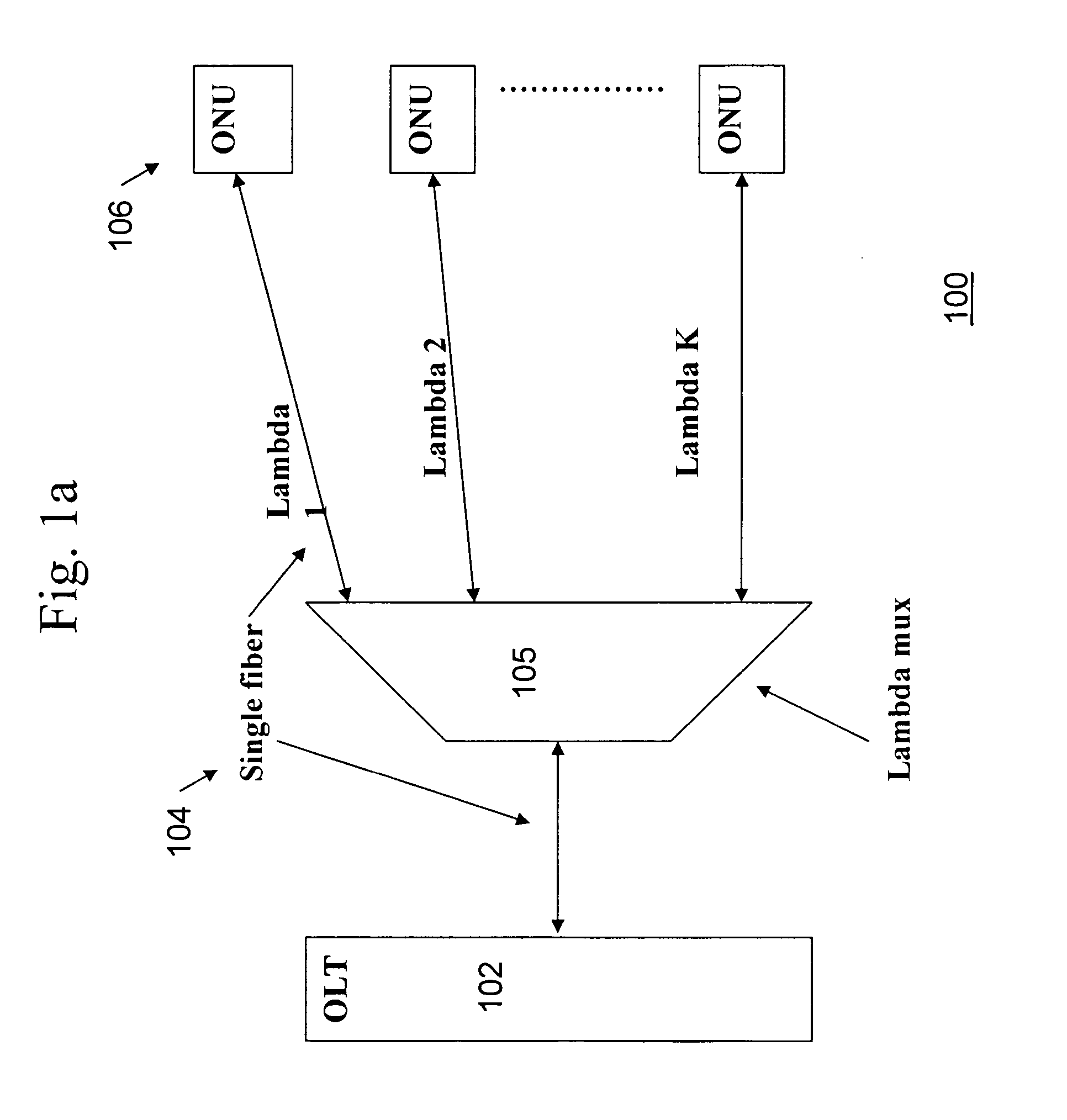
[0047] An exemplary PON system 100, in which the present invention may be implemented, is shown in FIG. 12a. One or more Optical Line Termination Units (OLTs) 102 provide the interface with data to be transmitted over the Optical Distribution Network (ODN) 104 to the Optical Network Unit (ONU) 106 portion of the PON. The passive elements of the PON are located in ODN 104 and may include single-mode fiber-optic cable, and passive optical devices such as splitters / couplers, connectors, multiplexers, and splices. In the example shown in FIG. 1a, ODN 104 includes lambda multiplexer 105 and a number of optical fibers.

[0048] The ONU 106 portion of the PON includes one or more ONUs that provide the interface between the customer's data, video, and telephony networks and the PON. The primary function of an ONU is to receive traffic in an optical format and convert it to the end user's desired format and to receive traffic from the end user and convert it to an optical format. Alternatively...


PUM


Abstract

Tuned lasers in the ONU's are eliminated in WDM PON by use of a burst mode transmission. An apparatus for communicating over a passive optical network comprises a transmitting portion operable to generate an optical signal comprising a first portion modulated with a first data signal and a second portion that is unmodulated and to transmit the optical signal over the passive optical network and a receiving portion operable to receive an optical signal comprising the second portion of the transmitted optical signal modulated with a second data signal.

Description

BACKGROUND OF THE INVENTION [0001] 1. Field of the Invention [0002] The present invention relates to an apparatus that eliminates the laser in an Optical Network Unit (ONU) in a Wave Division Multiplexed (WDM) Passive Optical Network (PON). [0003] 2. Description of the Related Art [0004] Optical networks have become a standard technology for the transport of information in the telecommunications industry. A number of different optical network standards have been defined, with each having advantages and disadvantages for different uses. Synchronous optical network (SONET) is one standard for optical telecommunications transport. SONET is often used for long-haul, metro level, and access transport applications. [0005] Another standard for optical telecommunications transport is passive optical networks (PONs). PONs are commonly used to address the last mile of the communications infrastructure between the service provider's central office, head end, or point of presence (POP) and busi...

Claims


Application Information

Patent Timeline
IPC IPC(8): H04B10/04H04B10/12
CPCH04B10/2587
Inventor BROLIN, STEPHEN J.
Owner FUJITSU LTD
Why Eureka
Try Eureka