System for dynamic control of automatic gain control take-over-point and method of operation

a technology of automatic gain control and take-over point, applied in the field of signal processing, can solve the problems of degrading the quality of the desired signal and over-driven input stages of the receiver, and achieve the effect of substantially reducing the disadvantages and problems associated with prior receivers

Inactive Publication Date: 2006-06-29
CSR TECH INC
View PDF13 Cites 17 Cited by
  • Summary
  • Abstract
  • Description
  • Claims
  • Application Information

AI Technical Summary

Benefits of technology

[0003] In accordance with the present invention, the disadvantages and problems associated with prior receivers have been substantially reduced or eliminated.
[0005] The following technical advantages may be achieved by some, none, or all of the embodiments of the present invention. A gain control circuit of a receiver is coupled to a first amplifier circuit and a second amplifier circuit. In general, the first amplifier circuit and the second amplifier circuit operate in conjunction to control the gain distribution of a modulated signal in a receiver. Each of the first amplifier circuit and the second amplifier circuit is associated with a particular gain profile that may be dynamically adjusted by the gain control circuit based upon a measured quality indicator of the modulated signal. In this regard, the receiver optimizes the quality of reception of the modulated signal despite the presence of strong adjacent channels. This adjustment to the gain profiles based upon the determined quality indicator can be done faster than if the adjustments are made solely upon the use of a quality indicator of a demodulated signal, such as the Bit Error Rate (BER) for digital signals. Moreover, the adjustments to the gain profiles are performed in small increments or decrements so that the gain control circuit can maintain a lock on the modulated signal.

Problems solved by technology

One problem with receiving television signals is the presence of strong adjacent channels surrounding a channel-of-interest.
However, when using the default TOP in the presence of strong adjacent channels, the input stages of the receiver can be overdriven and the quality of the desired signal can be degraded.

Method used


Image

  • System for dynamic control of automatic gain control take-over-point and method of operation
  • System for dynamic control of automatic gain control take-over-point and method of operation
  • System for dynamic control of automatic gain control take-over-point and method of operation

Examples


Embodiment Construction

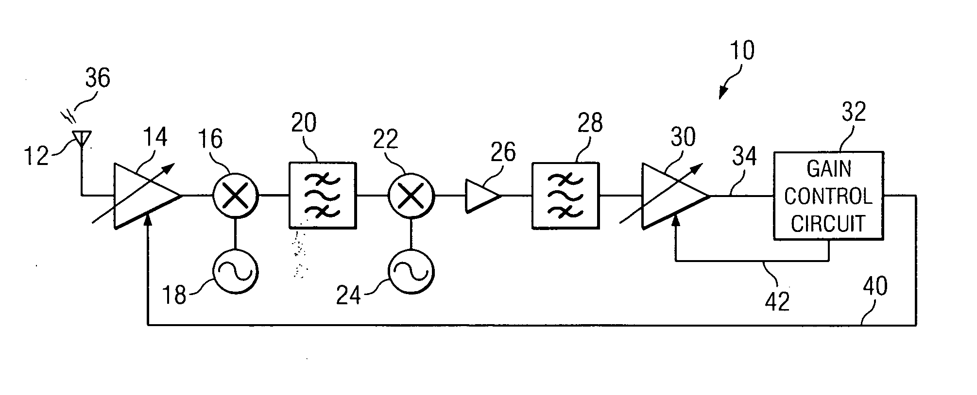
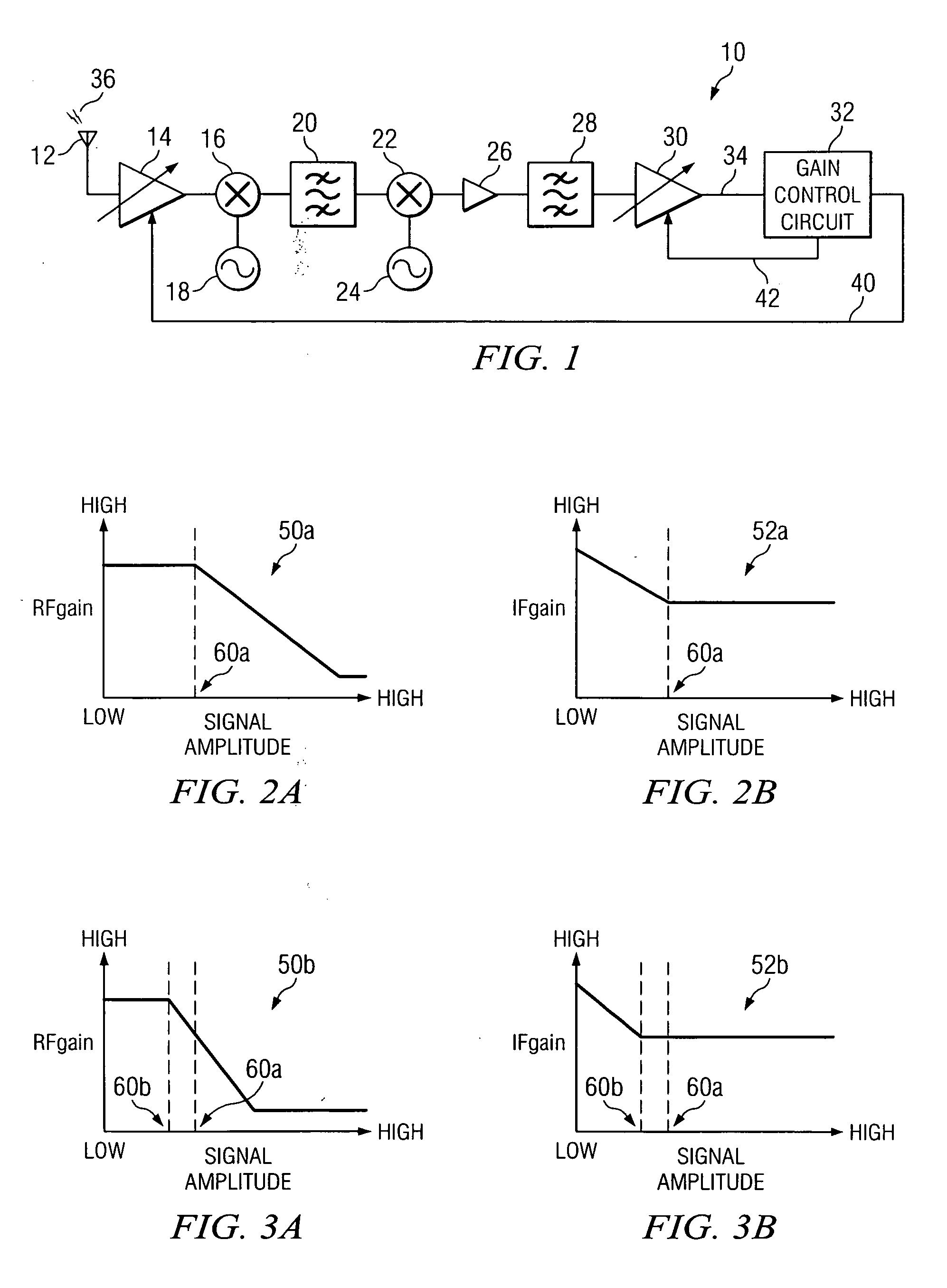
[0015]FIG. 1 illustrates one embodiment of a receiver 10 that includes an input device 12 coupled to a first amplifier circuit 14. Although FIG. 1 is illustrated and detailed with respect to a particular dual conversion tuner architecture for receiver 10, it should be understood that any suitable single, dual, or direct conversion tuner architecture may be used for receiver 10 without departing from the scope of this disclosure. Therefore, while a particular example of receiver 10 is illustrated and described herein, other architectures for receiver 10 are applicable. Referring to FIG. 1, a first mixer 16 is coupled to first amplifier circuit 14 and a first local oscillator 18. A first filter 20 is coupled to first mixer 16 and a second mixer 22, which is further coupled to a second local oscillator 24. An amplifier 26, such as a low noise amplifier (LNA), couples second mixer 22 to a second filter 28. Receiver 10 further comprises a second amplifier circuit 30 coupled to second fil...


PUM


Abstract

A receiver for processing a signal comprises a first amplifier circuit and a second amplifier circuit. The first amplifier circuit is operated in association with a first gain profile. The second amplifier circuit is operated in association with a second gain profile. The receiver further comprises a gain control circuit that determines a quality indicator associated with a modulated signal. The gain control circuit adjusts the first gain profile and the second gain profile based at least in part upon the determined quality indicator.

Description

TECHNICAL FIELD OF THE INVENTION [0001] This invention relates in general to signal processing, and more particularly to a system for dynamic control of automatic gain control take-over-point. BACKGROUND OF THE INVENTION [0002] One problem with receiving television signals is the presence of strong adjacent channels surrounding a channel-of-interest. Those adjacent channels are not taken into account when determining the gain of a receiver. By default, therefore, the gain of the two or more variable gain stages of a receiver are set to achieve the best sensitivity for the receiver. Typically, the gain of a first variable gain stage in the receiver is kept at a maximum as long as possible. The following variable gain stage(s) may be used to adjust the signal level according to the input level required by the demodulator. Only when the level of the desired signal becomes too strong is the gain of the first variable gain stage reduced to keep the signal levels within the linear range o...

Claims


Application Information

Patent Timeline
Patent Type & Authority Applications(United States)
IPC IPC(8): H04B1/06H04B7/00
CPCH03G3/3068H03G2201/103H03G2201/706H03G2201/305H03G2201/307H03G2201/204H03G3/30H04B1/10H04L1/00
Inventor HENNIG, ANDREAS G.
Owner CSR TECH INC
Why Eureka
Try Eureka