
Electronic blood pressure monitor and blood pressure measuring system

Active Publication Date: 2006-06-29
OMRON HEALTHCARE CO LTD
View PDF7 Cites 38 Cited by
  • Summary
  • Abstract
  • Description
  • Claims
  • Application Information

AI Technical Summary

Benefits of technology

[0009] An object of this invention is to provide an electronic blood pressure monitor which makes it possible to link blood pressure data to the conditions for measurement with higher precision, as well as a blood pressure measuring system.
[0015] Preferably, the selection portion is also used as an operation portion which is externally operated for instructing the start of measurement, and therefore, the configuration of the apparatus which is used both as the selection portion of the conditions for measurement and the measurement start instructing portion can be simplified.
[0031] In addition, selection of the conditions for measurement is also used as an instruction of the start of measurement, and thus, it is not necessary to input conditions for measurement separately for every measurement, and therefore, input of the conditions for measurement can be prevented from being forgotten, and incorrect input of the conditions for measurement can also be prevented.
[0032] In addition, an evaluation amount is calculated on the basis of the mutual relationship between a group of data on blood pressure that has been measured under the same conditions for measurement, which are stored in the memory portion as described above, and a group of data on blood pressure that has been measured under different conditions for measurement, and therefore, miscalculation of the evaluation amount caused by incorrect linkage of the measurement results to the conditions for measurement due to incorrect setting of the clock inside the electronic blood pressure monitor can be prevented.
[0033] In addition, it is possible for a patient to set conditions for measurement (such as after waking up, before sleeping and the like) which are appropriate for his / her life cycle via the selection portion in the case where types of conditions for measurement, such as after waking up, before sleeping, normal and the like, are provided, and therefore, even those such as shift workers, whose life cycle, including the time for waking up and sleeping, is different from ordinary people, can use data on blood pressure and the conditions for measurement which are linked to and stored in the memory portion, so that the evaluation value which correctly reflects the life cycle of the patient can be calculated.
[0034] In addition, it becomes unnecessary to separately input conditions for measurement for every measurement, as described above, and therefore, input of conditions for measurement can be prevented from being forgotten and incorrect input of conditions for measurement can also be prevented, and as a result, the evaluation amount can be prevented from being miscalculated.

Problems solved by technology

In addition, problems remain, such that the risk value is calculated on the basis of the time slot when blood pressure is measured, even in the case of a person such as a shift worker whose life cycle, including waking time and sleeping time, is different from ordinary people, and therefore, the risk value deviates from the risk value that is calculated from the true measured values after waking up and before sleeping.
Therefore, the condition input switches must be operated for every measurement, making switching operation troublesome.
In addition, problems remain, such that the correct risk value is not calculated when incorrect conditions for measurement are linked to the measured values because of the user forgetting to operate the condition input switches.

Method used


Image

  • Electronic blood pressure monitor and blood pressure measuring system
  • Electronic blood pressure monitor and blood pressure measuring system
  • Electronic blood pressure monitor and blood pressure measuring system

Examples


Embodiment Construction

[0046] In the following, the embodiments of this invention are described in detail in reference to the drawings. In the following descriptions, the same symbols are attached to parts and components that are the same. The names and functions of these are also the same. Accordingly, detailed descriptions for these are not repeated.

(Configuration)

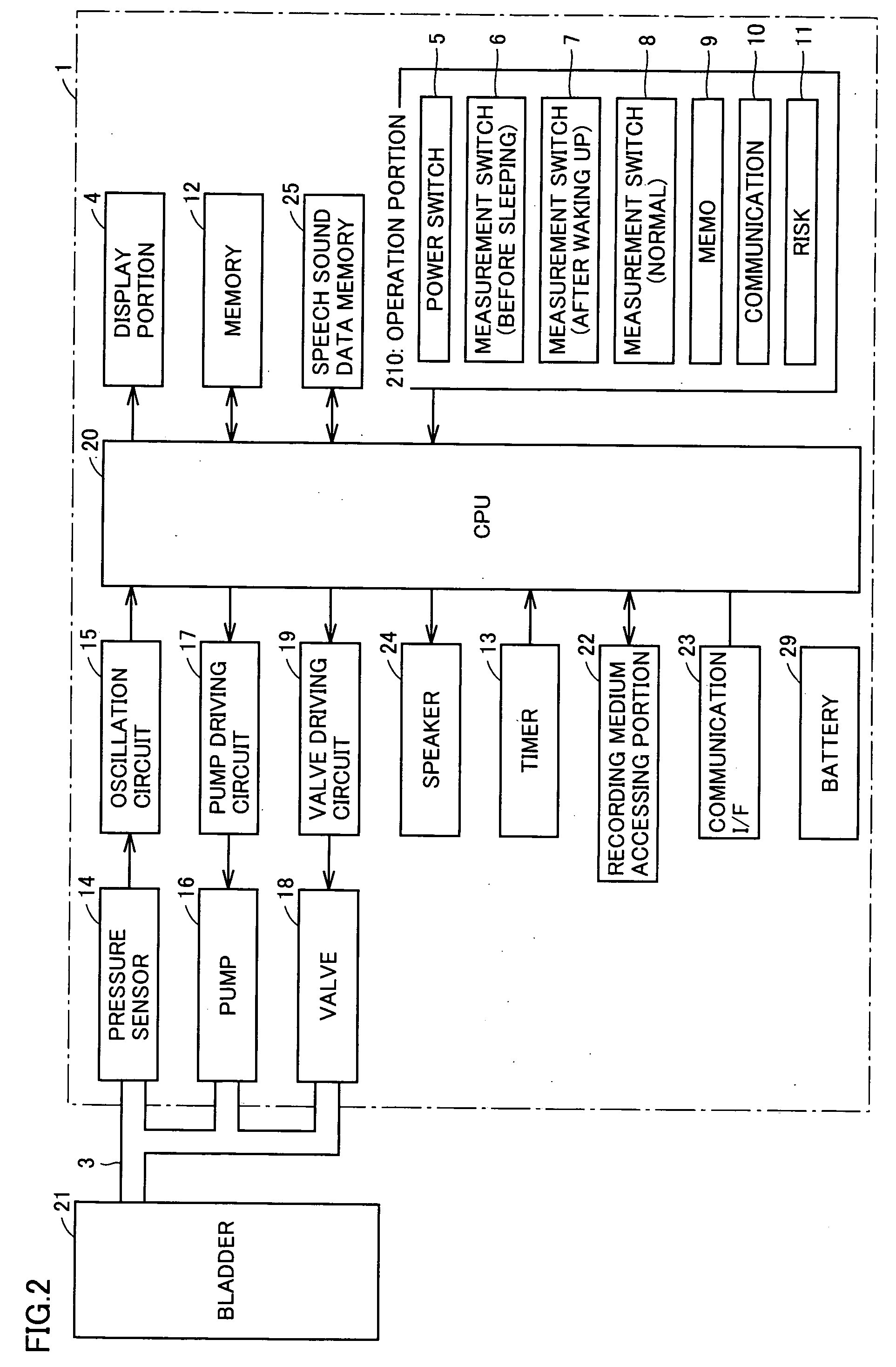
[0047] In reference to FIG. 1, an electronic blood pressure monitor according to the present embodiment is provided with a blood pressure monitor main body 1, a cuff 2 for applying pressure by means of air pressure which is attached to the part of a patient where blood pressure is measured, and an air tube 3 for connecting blood pressure monitor main body 1 to cuff 2.

[0048] Blood pressure monitor main body 1 has a display portion 4 that is provided so that a patient can confirm the content of display, a power switch 5, measurement switches 6, 7 and 8, a memo switch 9, a communication switch 10 and a risk display switch 11 that are provided...


PUM


Abstract

When a predetermined condition for measurement is selected from a plurality of conditions for measurement by operating one of measurement switches before measuring the blood pressure, a pressure begins to be applied to a bladder in response to the selection and the measurement of the blood pressure starts. The measured data of the blood pressure and the selected condition for measurement are linked to each other and stored in a memory. Because the measurement of the blood pressure starts upon selection of the predetermined condition by operating one of the measurement switches, one operation can serve both as switching to instruct the starting of the measurement and selecting the predetermined condition for measurement. Thus, an additional operation for inputting a condition for measurement is not necessary, and this makes it possible to prevent forgetting to input or incorrectly inputting a condition for measurement from occurring.

Description

BACKGROUND OF THE INVENTION [0001] 1. Field of the Invention [0002] This invention relates to an electronic blood pressure monitor and a blood pressure measuring system, and in particular, to an electronic blood pressure monitor which can measure and record information specifically on cardiovascular risk, as well as a blood pressure measuring system. [0003] 2. Description of the Background Art [0004] Blood pressure is a barometer for analyzing cardiac function, and risk analysis on the basis of blood pressure is effective for preventing cardiovascular system diseases, such as, for example, cerebral strokes, heart failure and myocardial infarction. For example, there is a cause and effect relationship between the surge in blood pressure that occurs between one hour and one and a half hours after waking up, which is referred to as morning surge, and cerebral stroke, and it is necessary to grasp the reciprocal relation between changes in blood pressure and health, for risk analysis of ...

Claims


Application Information

Patent Timeline
IPC IPC(8): A61B5/02A61B5/022
CPCA61B5/022A61B5/7475A61B2560/0295A61B5/02
Inventor SAWANOI, YUKIYANAKANISHI, HIROYATANAKA, TAKAHIDESHIRASAKI, OSAMU
Owner OMRON HEALTHCARE CO LTD
Learn More