Fan-driven heat dissipating device with enhanced air blowing efficiency

Inactive Publication Date: 2006-07-06
INVENTEC CORP
View PDF11 Cites 7 Cited by
  • Summary
  • Abstract
  • Description
  • Claims
  • Application Information

AI Technical Summary

Benefits of technology

[0008] The fan-driven heat dissipating device according to the invention is characterized by the provision of a secondary air outlet on the lateral side of the casing beside a primary air outlet, which allows part of the radially-flowing air stream to exit the casing laterally from the secondary air outlet, so that frict

Problems solved by technology

Integrated circuit devices, such as CPU (Central Processing Unit) or logic circuit chips, would normally produce large amounts of heat due to consumption of electrical power during operation.
If this heat is undissipated and accumulated within the chip, it would result in burnout of electrical components in the, chip, causing the chip to fail to operate normally.
One drawback to the aforesaid patent, howe

Method used


Image

  • Fan-driven heat dissipating device with enhanced air blowing efficiency
  • Fan-driven heat dissipating device with enhanced air blowing efficiency
  • Fan-driven heat dissipating device with enhanced air blowing efficiency

Examples


Embodiment Construction

[0014] The fan-driven heat dissipating device with enhanced air blowing efficiency according to the invention is disclosed in full details by way of preferred embodiments in the following with reference to the accompanying drawings.

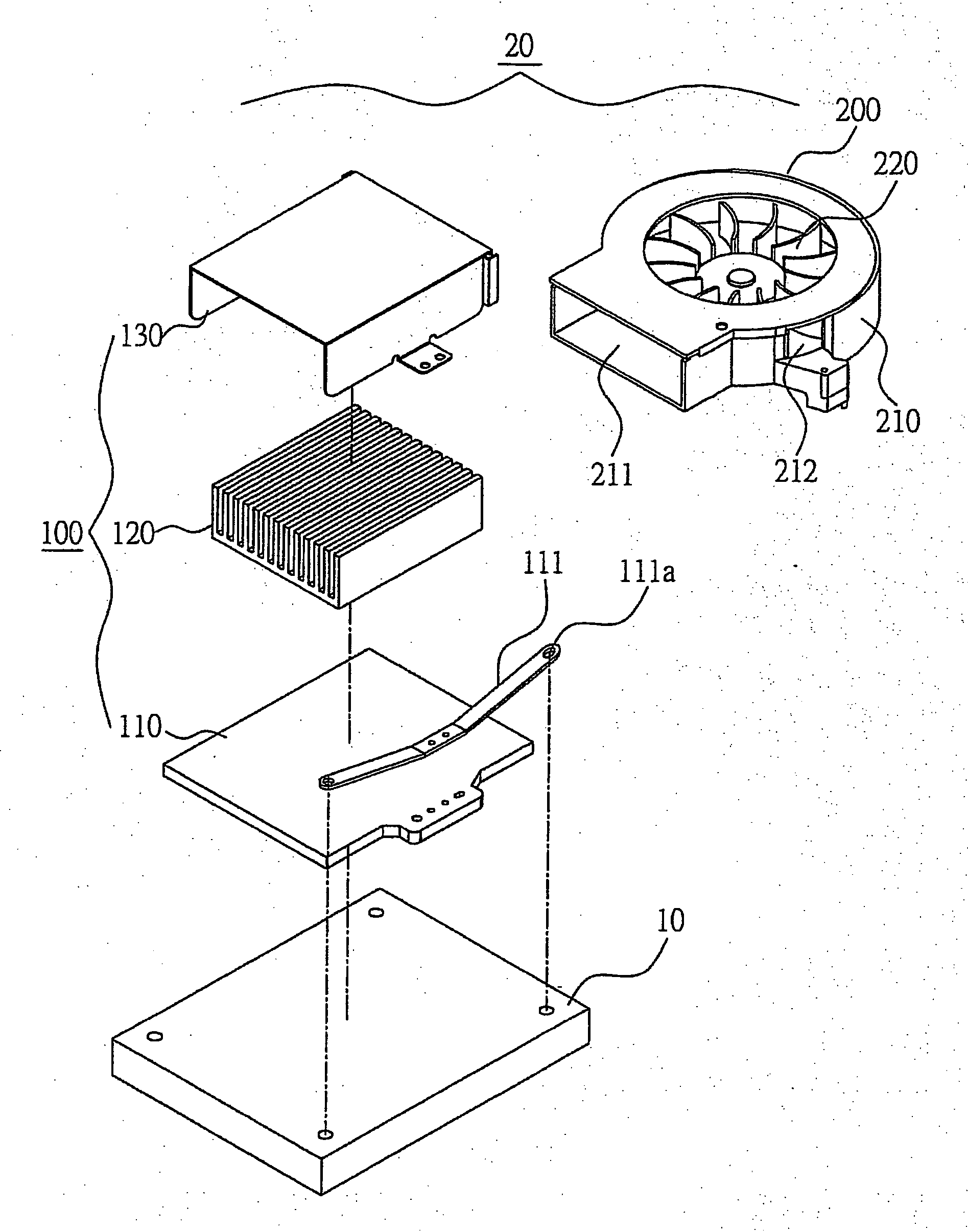
[0015]FIG. 1 is a schematic diagram showing an explode perspective view of the fan-driven heat dissipating device of the invention 20 with an integrated circuit device 10. In actual application, the fan-driven heat dissipating device of the invention 20 is used in conjunction with the integrated circuit device 10, which is for example a CPU (Central Processing Unit) chip or a logic circuit chip, for dissipating the heat produced by the integrated circuit device 10 during operation.

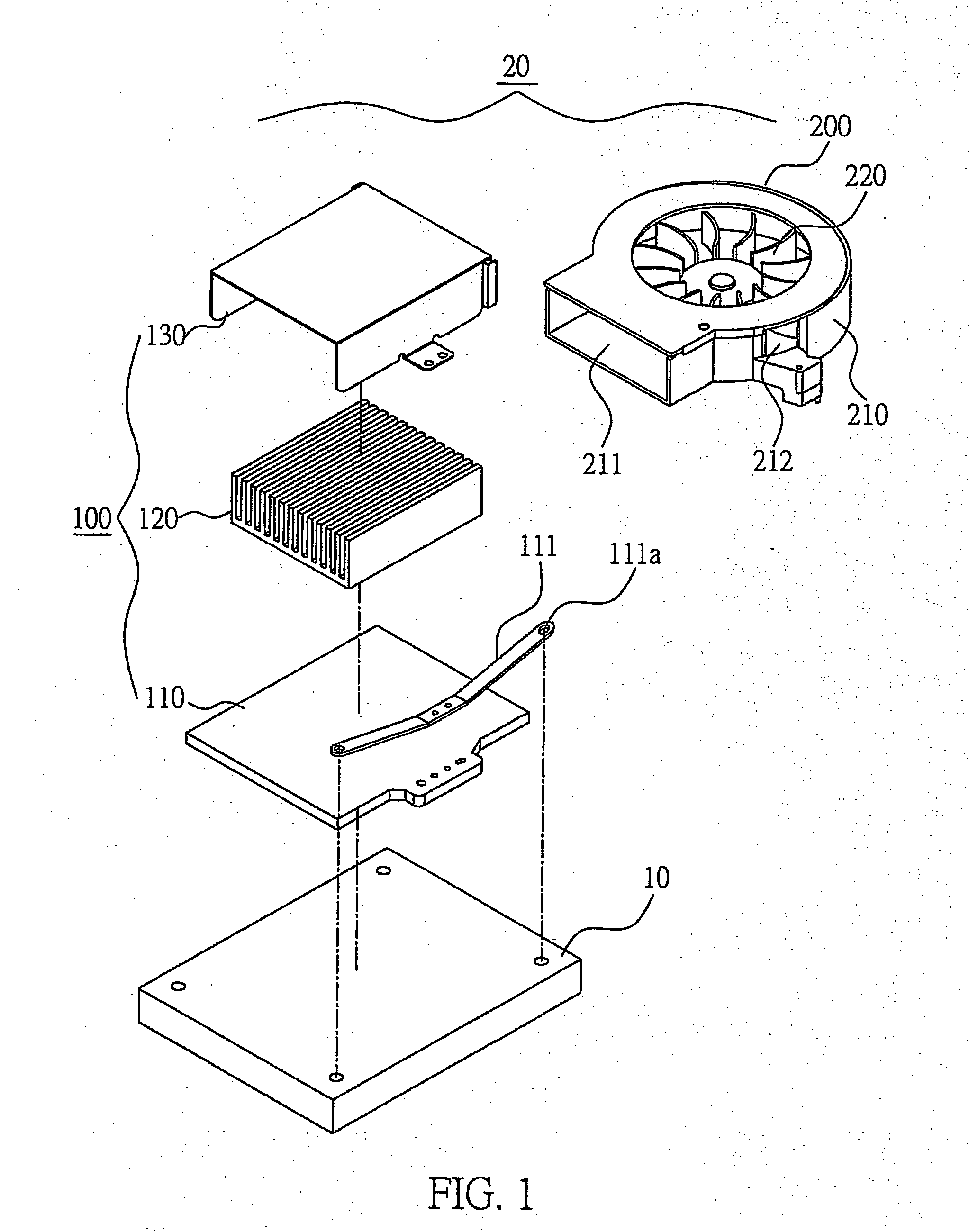
[0016] As shown in FIG. 1, the fan-driven heat dissipating device of the invention 20 comprises: (a) a thermally-conductive module 100; and (b) a fan module 200; and wherein, as also shown in FIG. 2, the thermally-conductive module 100 is composed of: (a1) a thermally-conducti...


PUM


Abstract

A fan-driven heat dissipating device with enhanced air blowing efficiency is proposed, which is designed for use in conjunction with an integrated circuit device for dissipating the heat produced by the integrated circuit device during operation, and which is characterized by the provision of a secondary air outlet on the lateral side of the casing beside a primary air outlet, which allows part of the radially-flowing air stream to exit the casing laterally from the secondary air outlet, so that frictional loss due to the air flow striking against the inner wall of the casing can be reduced, allowing the fan module to provide a more enhanced air blowing efficiency than the prior art. This feature allows the fan-driven heat dissipating device of the invention to provide a more enhanced heat-dissipating efficiency than the prior art.

Description

FIELD OF THE INVENTION [0001] This invention relates to heat dissipating technology, and more particularly, to a fan-driven heat dissipating device with enhanced air blowing efficiency which is designed for use in conjunction with an integrated circuit device, for dissipating the heat produced by the integrated circuit device during operation. BACKGROUND OF THE INVENTION [0002] Integrated circuit devices, such as CPU (Central Processing Unit) or logic circuit chips, would normally produce large amounts of heat due to consumption of electrical power during operation. If this heat is undissipated and accumulated within the chip, it would result in burnout of electrical components in the, chip, causing the chip to fail to operate normally. One solution to this problem is to provide a heat-dissipating device, such as an electrical fan, for dissipating the heat produced by the chip during operation. For example, network servers or desktop computers are customarily mounted with one or mor...

Claims


Application Information

Patent Timeline
IPC IPC(8): H05K7/20
CPCH01L23/4006H01L23/467H01L2924/0002H01L2924/00
Inventor CHOU, PETEWANG, FRANK
Owner INVENTEC CORP
Why Eureka
Try Eureka