Simple, mechanism-free device, and method to produce vortex ring bubbles in liquids

a technology of vortex ring and gas, which is applied in mechanical equipment, transportation and packaging, and carbureting air, etc., can solve the problems of sudden acceleration and spurt out of the nozzle outlet with considerable speed, and the difference between the head and the nozzle is even larger

Active Publication Date: 2006-07-06
THOMAS ANDREW SYDNEY WITHIEL
View PDF6 Cites 28 Cited by
  • Summary
  • Abstract
  • Description
  • Claims
  • Application Information

AI Technical Summary

Benefits of technology

[0025] It is therefore an object of the present invention to provide a simple device that employs a method such that once supplied with a source of gas at the appropriate pressure, it will endlessly produce vortex ring bubbles, one after the other, of that gas in a liquid medium.

Problems solved by technology

However, as the meniscus rises, the difference in the liquid levels increases, so the effective head is increased, and this causes the meniscus to move faster, which causes the head difference to be even larger, which even further accelerates the meniscus travel up the nozzle.
The consequence is that the gas rising up the nozzle might start relatively slowly, but then it suddenly accelerates and spurts out of the nozzle outlet with considerable speed.
As might be expected, the components do need to be sized properly in relation to one another, as improper sizing will just lead to gurgling or chaotic streams of bubbles, or intermittent bubbles with no coherence.
Firstly, the embodiments create the elevated pressure difference and conditions needed to rapidly accelerate the flow.
Secondly, they create a flow pulse that lasts for the required short duration.

Method used


Image

  • Simple, mechanism-free device, and method to produce vortex ring bubbles in liquids
  • Simple, mechanism-free device, and method to produce vortex ring bubbles in liquids
  • Simple, mechanism-free device, and method to produce vortex ring bubbles in liquids

Examples


Embodiment Construction

[0051] Technical Background

[0052] The following description is provided to enable any person skilled in the art to make and use the various embodiments of the invention, and to understand the method behind the operation of the various embodiments of the invention, and sets forth the best modes contemplated by the inventor of carrying out his invention. Various modifications, however, will remain readily apparent to those skilled in the art.

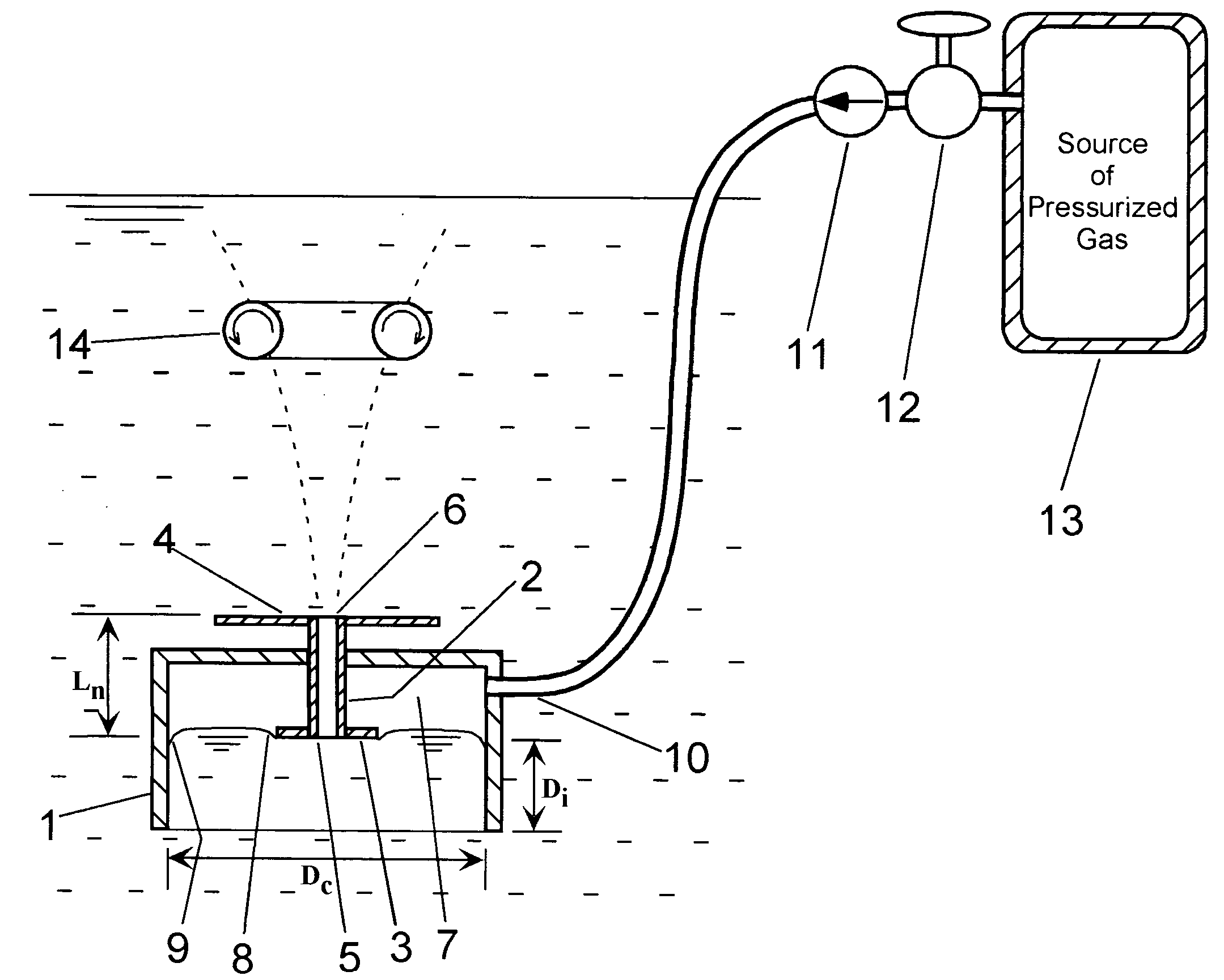
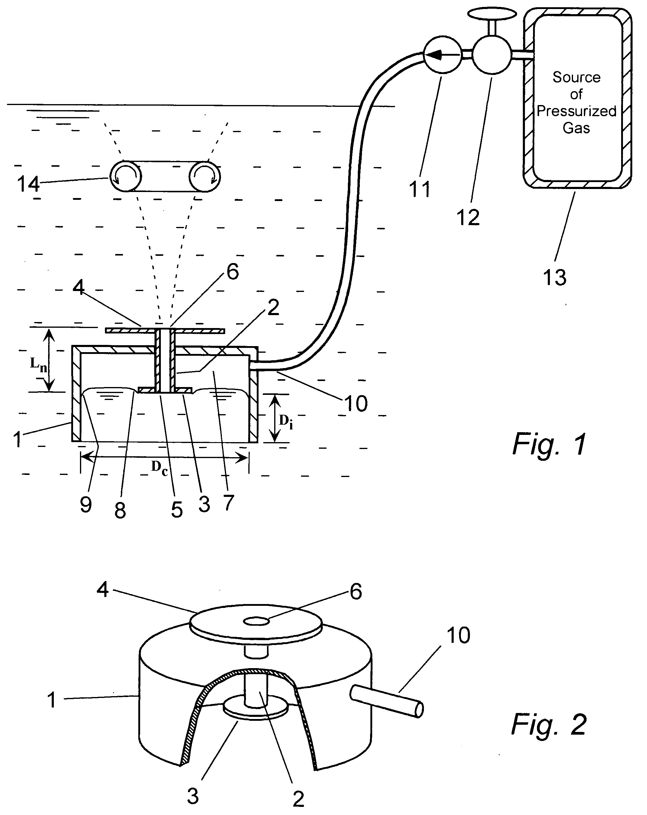
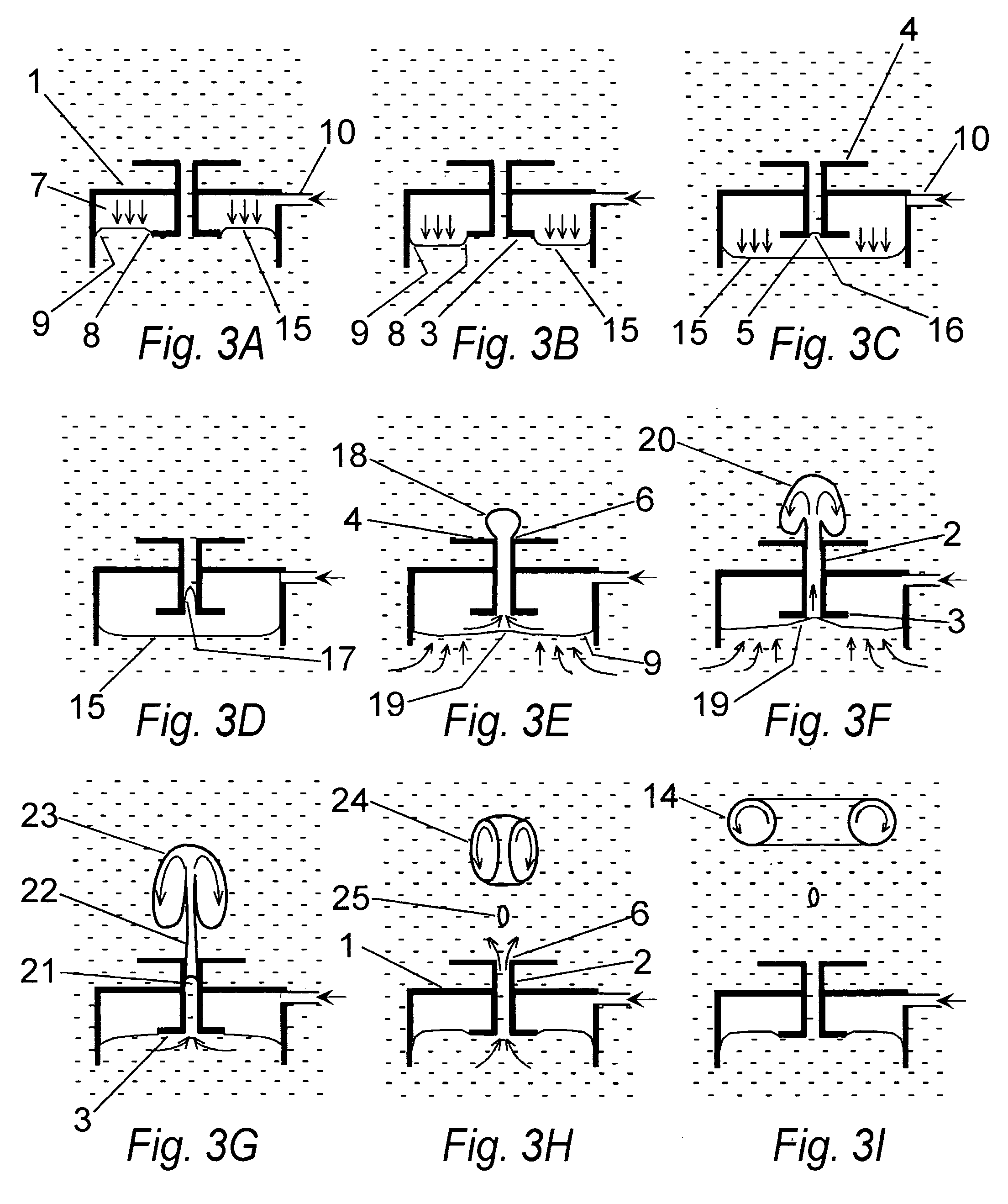
[0053]FIG. 1 depicts the basic embodiment of the invention for producing gas-filled vortex rings in a liquid medium. The salient features of this invention are captured by elements 1 through 10 shown in FIG. 1. The same device is shown in a perspective cutaway view in FIG. 2 and the physics of its operation is presented in the sequence depicted in FIGS. 3A through 3I. It is made of any material that is impervious to the liquid and can not be damaged by chemical reaction with the liquid. It consists of an inverted cup, 1, immersed below the surfa...


PUM

PropertyMeasurementUnit
volumeaaaaaaaaaa
wettingaaaaaaaaaa
pressureaaaaaaaaaa

Abstract

An apparatus and method are described that allows for the production of vortex-ring bubbles in a host liquid. A simple embodiment of the device consists of an inverted cup with a short nozzle protruding into it through the center of its end face. Circular plates are fixed to both open ends of the nozzle tube, which itself is positioned such that its lower end is at a higher level than the open end of the inverted cup. When cup is immersed in a liquid, open end down, and the inside of the cup is pressurized with an inflow of gas, a confined volume of gas will form inside the cup, and the liquid level in the cup will fall, and peel away from the nozzle lower end plate. The gas is exposed to the open lower end face of the nozzle, but does not enter the nozzle until the pressure has built up within the cup sufficiently to break the surface tension meniscus at the nozzle inlet. The gas then self accelerates up through the nozzle and rapidly exits at the upper end of the nozzle tube. The confined liquid level in the cup rises back up in response and enters the nozzle in a unique self-siphoning action shutting off further gas flow out the nozzle. The exiting gas bubble self organizes into a gas-filled, vortex ring. Alternatively, the exiting flow of gas can be captured in a second conical nozzle and buoyantly directed to the throat of the nozzle where it undergoes the same self acceleration and self siphoning to form a vortex ring at the throat exit. Other different embodiments of the device that all operate under the same method of intermittent breaking of surface tension forces followed by self acceleration and self siphoning to generate a vortex ring bubble are described. The advantages of the device are that it is mechanically simple, easy to manufacture, has no moving parts, will not wear out, and does not require any operator intervention in order to function.

Description

BACKGROUND OF THE INVENTION [0001] 1. Technical Field [0002] This invention describes a simple apparatus and method for producing vortex ring bubbles of a gas in a host liquid. Once provided with a source of compressed gas, the basic geometry of the device establishes the conditions such that it will repetitively and endlessly produce gas-filled, vortex ring bubbles in a host liquid, at a rate determined only by the pressure and in-flow rate of the gas source. The device requires no high-tolerance components and is low-cost to manufacture. It has no moving parts, and will not wear out. It requires no periodic maintenance servicing, no human intervention, and no fine adjustments to sustain its operation. [0003] 2. Description of the Prior Art [0004] Some forty years ago it was first reported that it is possible to generate rising toroidal ring-shaped bubbles, or ring bubbles as they are sometimes called, of gas within liquids. These are in fact vortex rings in the liquid, in which th...

Claims


Application Information

Patent Timeline
Patent Type & Authority Applications(United States)
IPC IPC(8): B01F3/04
CPCB01F3/04241B01F13/0222B01F13/0283B01F2003/04872F15D1/009B01F23/2312B01F23/237611B01F33/403B01F33/409
Inventor THOMAS, ANDREW S. W.
Owner THOMAS ANDREW SYDNEY WITHIEL
Why Eureka
Try Eureka