Integrated PLL loop filter and charge pump

a technology of charge pump and loop filter, which is applied in the direction of electrical equipment, pulse automatic control, etc., can solve the problems of jitter in the clock and insufficient current balan

Inactive Publication Date: 2006-07-06
SILICON LAB INC
View PDF8 Cites 13 Cited by
  • Summary
  • Abstract
  • Description
  • Claims
  • Application Information

AI Technical Summary

Benefits of technology

[0005] The present invention disclosed and claimed herein, in one aspect thereof, comprises a charge pumped phase locked loop circuit (PLL). The PLL includes a phase detector for detecting the phase error between a reference clock and an output clock to generate a phase error signal. A charge pump is provided that is controlled by the phase error signal to either source current to an intermediate control node or to sin

Problems solved by technology

Therefore, if the voltage changes, i.e., it is not constant, there is a possibility that the currents will not be ba

Method used


Image

  • Integrated PLL loop filter and charge pump
  • Integrated PLL loop filter and charge pump
  • Integrated PLL loop filter and charge pump

Examples


Embodiment Construction

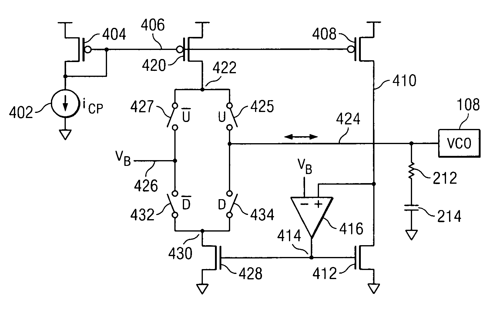
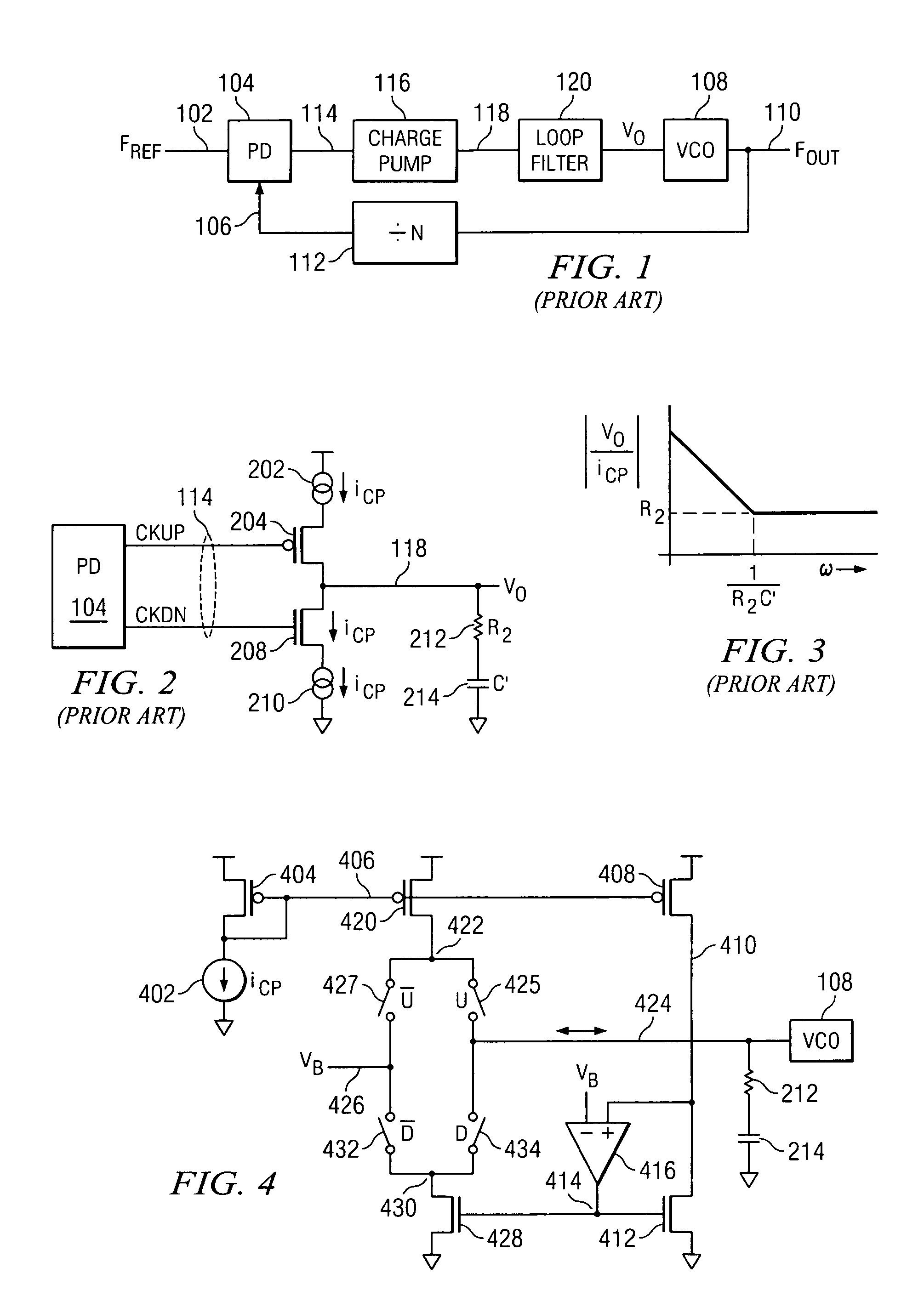
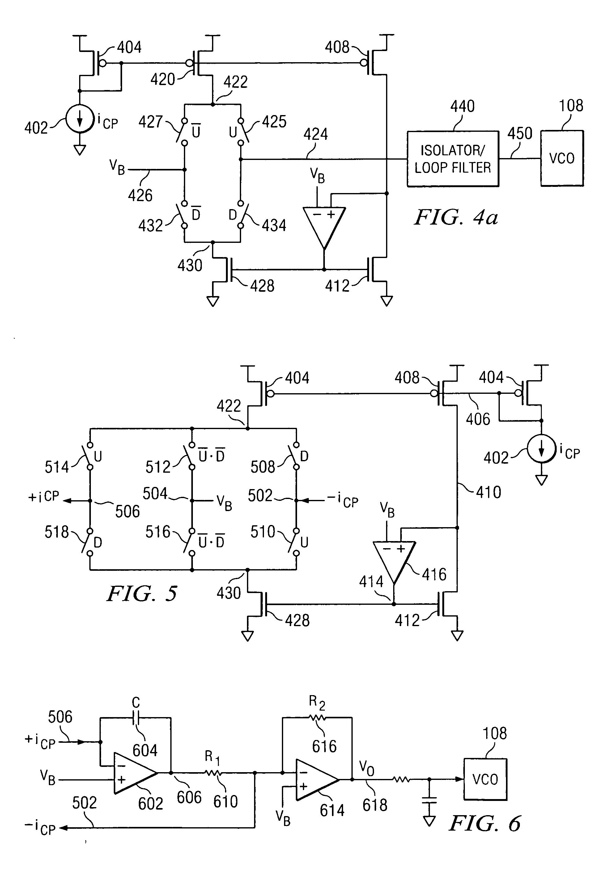
[0015] Referring now to the drawings, and more particularly to FIG. 1, there is illustrated a diagram of a prior art phase lock loop. The phase lock loop receives a reference frequency on a frequency input 102 that is input to a phase detector 104. The phase detector 104 is operable to compare the phase of the reference clock on input 102 with a variable clock frequency associated with an output clock on an input 106. This variable frequency on the input 106 is generated by a voltage controlled oscillator (VCO) 108 that is operable to generate a frequency FOUT on an output 110. This can be at a frequency that is greater than the frequency of the reference clock on the input 102. If so, the output of the VCO 108 on output 110 is divided by a divide block 112 to provide a divided down clock frequency at substantially the frequency of the reference clock, on the line 106.

[0016] The phase detector 104 is operable to generate a phase error on a line 114. This phase error provides a cont...


PUM


Abstract

A charge pumped phase locked loop circuit (PLL) is disclosed that includes a phase detector for detecting the phase error between a reference clock and an output clock to generate a phase error signal. A charge pump is provided that is controlled by the phase error signal to either source current to an intermediate control node or to sink current therefrom. An isolation circuit maintains the intermediate control node at a virtual AC reference voltage such that it remains at substantially the same voltage during the sourcing of current thereto or sinking of current therefrom, the isolation circuit generating a control voltage on the output thereof to control the frequency of the output clock. A loop filter is provided for filtering the control voltage.

Description

CROSS-REFERENCE TO RELATED APPLICATIONS [0001] This application is related to pending U.S. Provisional Patent Application Ser. No. 60 / 640,488, filed on Dec. 30, 2004 (Atty. Dkt. No. CYGL-26,989) entitled “INTEGRATED PLL LOOP FILTER AND CHARGE PUMP.”TECHNICAL FIELD OF THE INVENTION [0002] The present invention pertains in general to phase lock loops (PLLs) and, more particularly, to the operation of the charge pump and loop filter portion of the PLL. BACKGROUND OF THE INVENTION [0003] Phase lock loops utilize a phase detector for comparing the phase of a reference clock with that of an output clock that utilizes a voltage controlled oscillator (VCO) to generate a phase error that varies the control voltage on the input to the VCO. By adjusting this voltage, the phase of the VCO can be locked the phase of the reference clock. Typically, some type of loop filter is disposed between the phase detector and the VCO. In a charge pump PLL, a typical phase detector generates control voltages...

Claims


Application Information

Patent Timeline
IPC IPC(8): H03L7/00
CPCH03L7/0896H03L7/093
Inventor MANETAKIS, KONSTANTINOSCONSTANTINIDIS, NICOLAS
Owner SILICON LAB INC
Why Eureka
Try Eureka