Precision inductive devices and methods

a precision inductive device and inductance technology, applied in the direction of printed inductance, inductance details, inductances, etc., can solve the problem of low ripple in output voltage, lack of simplified and low-cost high-performance inductor configuration, and prior art solutions that lack substantial uniformity in inductance, so as to reduce flux leakage effects and improve balancing of inductance across the device. , the effect of reducing the effect of flux leakag

Active Publication Date: 2006-07-06
PULSE ELECTRONICS
View PDF35 Cites 197 Cited by
  • Summary
  • Abstract
  • Description
  • Claims
  • Application Information

AI Technical Summary

Benefits of technology

[0031] In a second aspect of the invention, an improved multi-inductor device is disclosed. In one embodiment, the inductors are arranged in a linear disposition within a core, with the two inductors on the ends of the core having different magnetic path characteristics than the other inductors. In one variant, the different characteristic(s) comprise a different gap cross-sectional area (A), which alters the reluctance and accordingly raises the inductance of these two end devices. This allows mitigation of flux leakage effects on the two end inductors, and accordingly better balance between the inductance values of all inductors in the device.
[0032] In a third aspect of the invention, an improved method of controlling the operation of a multi-inductor device is disclosed. In one embodiment, the method comprises creating a residue gap between at least two portions of a magnetically permeable core used in the device. The residue gap allows for precise control of the properties of each individual inductor, and hence better balancing of inductance across the device as a whole.
[0033] In a fourth aspect of the invention, an improved method of controlling the operation of a multi-inductor device is disclosed. In one embodiment, the method comprises disposing the gap relative to the windings during manufacture in order to mitigate the interaction between the gap flux and the windings, thereby reducing eddy current and other potentially deleterious effects.
[0034] In a fifth aspect of the invention, an improved method of controlling the operation of a multi-inductor device is disclosed. In one embodiment, the method comprises controlling one or more parameters associated with the magnetic pathways for one or more of the inductors in order to more evenly balance the inductance of all the devices. In one variant, the act of controlling comprises setting the gap cross-sectional area for the two “end” inductors of the device, thereby reducing reluctance (R) and allowing for an increased inductance of the end inductors.

Problems solved by technology

This results in lower ripple in the output voltage.
Despite the foregoing broad variety of prior art inductor configurations, there is a distinct lack of a simplified and low-cost, high performance inductor configuration that provides a high degree of uniformity (tolerance) as well as great precision.
Even so-called “coupled” prior art solutions lack substantial uniformity in the inductances and other performance attributes of the individual constituent inductors.

Method used


Image

  • Precision inductive devices and methods
  • Precision inductive devices and methods
  • Precision inductive devices and methods

Examples


Embodiment Construction

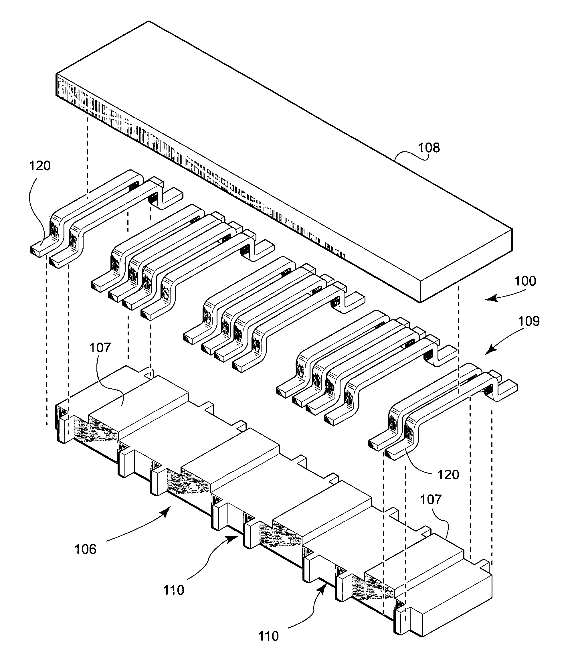
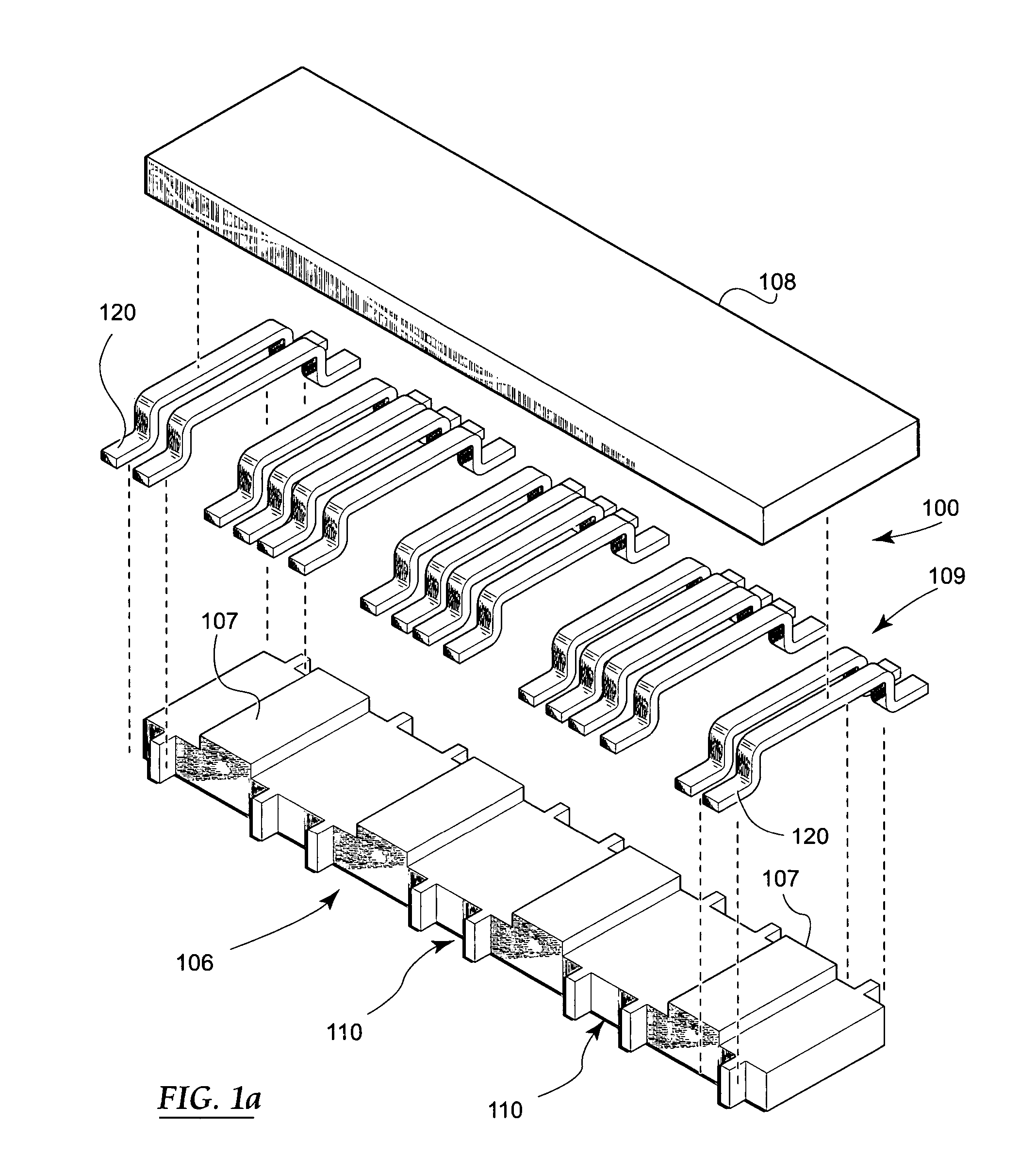
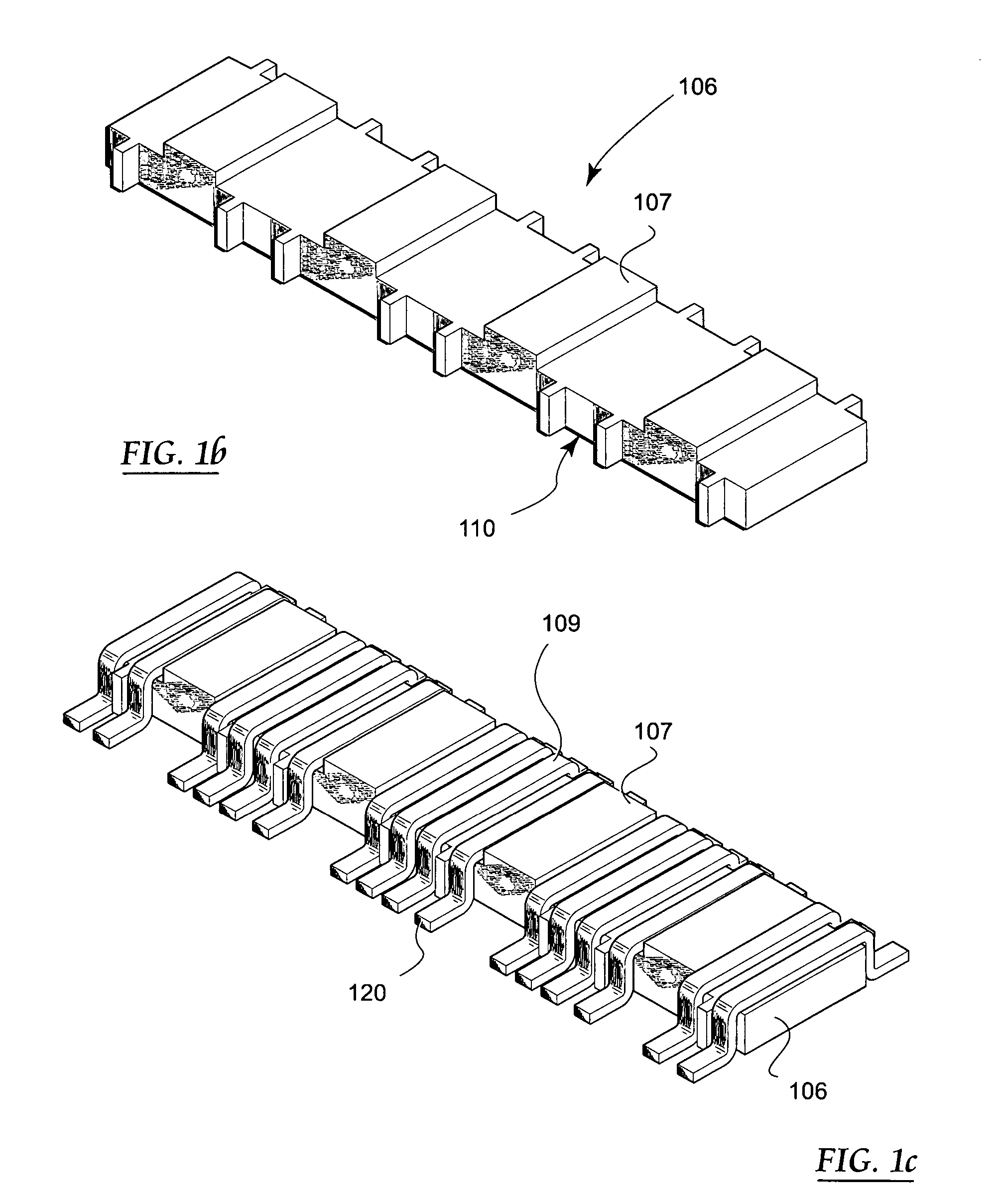
[0059] Reference is now made to the drawings wherein like numerals refer to like parts throughout.

[0060] As used herein, the term “magnetically permeable” refers to any number of materials commonly used for forming inductive cores or similar components, including without limitation various formulations made from ferrite.

[0061] As used herein, the term “winding” refers to any type of conductor, irrespective of shape, cross-section, or number of turns, which is adapted to carry electrical current.

Overview

[0062] The present invention provides, inter alia, improved inductive apparatus and methods for manufacturing and utilizing the same.

[0063] As is well, known, a high degree of uniformity (tolerance) is often desirable for electronic circuit elements, especially were two or more such components are disposed in a common circuit. For example, in power supply applications, the recent trend has been to distribute current or load associated with components in the power supply across m...


PUM

PropertyMeasurementUnit
elevationsaaaaaaaaaa
grain sizeaaaaaaaaaa
magneticaaaaaaaaaa

Abstract

A low cost, low profile, small size and high performance inductive device for use in, e.g., electronic circuits. In one exemplary embodiment, the device includes a ferrite core comprising multiple inductors and optimized for electrical and magnetic performance. Improvements in performance are obtained by, inter alia, control of the properties of the gap region(s) as well as placement of the windings relative to the gap. The magnetic path properties of the inductors at the ends of the device are also optionally controllable so as to provide precise matching of inductances. Optionally, the device is also self-leaded, thereby simplifying its installation and mating to a parent device (e.g., PCB). Methods for manufacturing and utilizing the device are also disclosed.

Description

PRIORITY AND RELATED APPLICATIONS [0001] This application claims priority to U.S. Provisional Patent Application Ser. No. 60 / 606,330 filed Aug. 31, 2004 of the same title, which is incorporated herein by reference in its entirety. This application is generally related to the subject matter of U.S. patent application Ser. No. 10 / 990,915 filed Nov. 16, 2004 entitled “IMPROVED INDUCTIVE DEVICES AND METHODS”, which claims priority to U.S. Provisional Application Ser. No. 60 / 520,965 filed Nov. 17, 2003 of the same title, both incorporated herein by reference in their entirety.COPYRIGHT [0002] A portion of the disclosure of this patent document contains material that is subject to copyright protection. The copyright owner has no objection to the facsimile reproduction by anyone of the patent document or the patent disclosure, as it appears in the Patent and Trademark Office patent files or records, but otherwise reserves all copyright rights whatsoever. [0003] 1. Field of the Invention [0...

Claims


Application Information

Patent Timeline
Patent Type & Authority Applications(United States)
IPC IPC(8): H01F27/02
CPCH01F17/045H01F27/266H01F27/2804H01F27/2847H01F27/306H01F2017/002
Inventor DADAFSHAR, MAJIDMICHEL, FRANCISCO
Owner PULSE ELECTRONICS
Why Eureka
Try Eureka