Solar powered lamp

a solar energy and lamp technology, applied in the field of solar energy-powered lamps, can solve the problems of unpleasant direct viewing and little illumination, and achieve the effects of reducing brightness, reducing brightness, and substantial increases in apparent light outpu

Inactive Publication Date: 2006-07-06
MORTON RICHARD G +1
View PDF3 Cites 21 Cited by
  • Summary
  • Abstract
  • Description
  • Claims
  • Application Information

AI Technical Summary

Benefits of technology

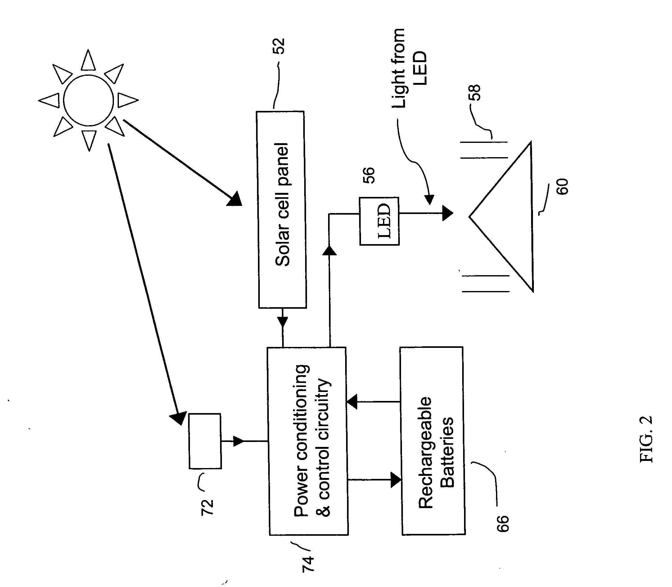
[0006] The present invention provides a improved solar powered LED-based lighting fixture providing substantial increases in the apparent light output compared to prior art solar powered LED-based lighting fixtures. This improvement in preferred embodiments results from the addition of inexpensive spherical lenses that create a large number of images of LED light sources, each image having substantially reduced brightness as compared to the real LED light source. These images with substantially reduced brightness result in beautiful patterns, and still appear very bright to human observers at night. In a preferred embodiment ten plastic 0.5-inch spherical lenses are positioned along the bottom edge of the cone at the bottom of the lamp. Each of these spherical lenses creates a double image of the single source LED, both very bright compared to the light coming from the same region in a lamp fixture w

Problems solved by technology

The LED is extremely bright so that direct viewing of it can be unpleasant.
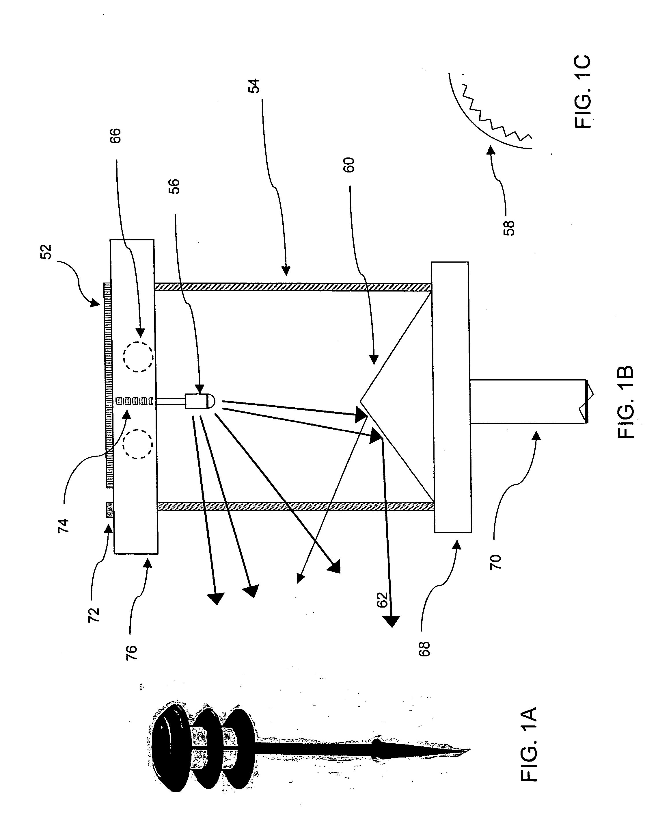
The primary problem with light fixtures of the type shown in FIGS. 1A, B and C is that the

Method used


Image

  • Solar powered lamp
  • Solar powered lamp
  • Solar powered lamp

Examples


first preferred embodiment

[0019] A first preferred embodiment of the present invention can be described by reference to FIGS. 3-6. An important optical element added to the existing device described in the Background Section for the purpose of enhancing the light distribution is shown in FIG. 3. This is a clear, transparent ½-inch diameter sphere made from plastic or glass that forms a widely distributed bright image of the source LED 56 close to the surface of the sphere. In FIG. 4, a top view shows that 10 of these ½-inch spheres are arrayed around the circumference of the inner wall of the 2¼ inch diameter transparent cylindrical lens. A space just smaller than the diameter of a single sphere is left in the array, so that there is no difficulty in loading the group of 10 spheres into the housing. The spheres naturally array themselves in the correct position at the circumference of lens 54 by the action of gravity and the conical reflector 60. No additional attachment is needed or desired.

[0020] Each sph...


PUM


Abstract

An improved solar powered LED-based lighting fixture providing substantial increases in the apparent light output compared to prior art solar powered LED-based lighting fixtures. This improvement in preferred embodiments results from the addition of inexpensive spherical lenses that create a large number of images of LED light sources, each image having substantially reduced brightness as compared to the real LED light source. These images with substantially reduced brightness result in beautiful patterns, that still appear very bright to a night time observer, because the LED source itself is in fact too bright to look at directly. In a preferred embodiment ten plastic 0.5-inch spherical lenses are positioned along the bottom edge of the cone at the bottom of lamp. Each of these spherical lenses creates multiple images of the single source LED, all nearly as bright as the source itself. As a result the perceived delivery of light intensity to an observer is multiplied by a factor of approximately 10 times. In other preferred embodiments, conventional primary cell alkaline batteries are used in place of rechargeable Nickel-Cadmium batteries, whereby the battery cost is cut in half and the energy storage capacity tripled. Applicant has discovered that the conventional primary cell alkaline batteries are safely and effectively recharged by the solar cell.

Description

BACKGROUND OF THE INVENTION [0001] Landscape lighting has long been popular as a nighttime enhancement to the grounds surrounding private homes or businesses. These generally require running wires underground to supply electrical power, and have typically employed conventional, incandescent tungsten filament lamps from which the radiated visible output energy is about one percent of the electrical power supplied. The remaining approximately 99% of the electrical energy is converted to heat and longer wavelength invisible radiation. Much higher efficiency light emitting diode (LED) sources of illumination are now available from many sources and are widely used in industrial and consumer products. Solar cells are well known and are commercially available from many sources to convert sunlight to electrical energy for charging batteries. Electronic components are also available and well known for efficiently charging batteries with solar power sources. These technologies have permitted ...

Claims


Application Information

Patent Timeline
IPC IPC(8): F21V33/00
CPCF21S8/081F21S9/037F21V5/041F21V7/0008F21V9/08F21V21/0824F21V23/0442F21W2131/10F21W2131/109F21Y2101/02F21V7/041F21Y2115/10Y02B20/72
Inventor MORTON, RICHARD G.ROSS, JOHN R.
Owner MORTON RICHARD G
Why Eureka
Try Eureka