Backlight system

a backlight system and backlight technology, applied in circuit optical details, lighting and heating apparatus, instruments, etc., can solve the problems of low practical value the printed board b>, and achieve the effect of simplifying the structure of the backlight system, miniaturizing the backlight system, and reducing the weight of the printed board 2

Active Publication Date: 2006-07-06
NICHIA CORP
View PDF8 Cites 7 Cited by
  • Summary
  • Abstract
  • Description
  • Claims
  • Application Information

AI Technical Summary

Benefits of technology

[0007] An LED is often used as the light-emitting source of the backlight system, and hence a miniaturized, thinned and long-lived backlight system can be achieved. If LEDs are used and it is desired to acquire white illumination light from the backlight system, three kinds of high-intensity LEDs, red (R), green (G) and blue (B) LEDs, are used, and these three kinds of LEDs are simultaneously lighted or lighted in a time sharing manner. The light from the three kind of LEDs is mixed and this mixed lights appears to be white light. White-light emitting LEDs comprising blue LEDs and fluorescent materials may be used instead of RGB LEDs. Each of the white-light emitting LEDs emits white light singularly.
[0008] In particular, if white-light emitting LEDs are used in a backlight system, a structure of the backlight system is simplified, and miniaturization of the backlight system is also accomplished.
[0009] FIG.4 illustrates a conventional backlight system as disclosed in Japanese Utility Model Laid-Open No. S64-49886, for reference. The backlight system 1 includes an insulative printed board 2, a plurality of LEDs 3 disposed on an upper surface of the printed board 2, a reflective frame 4 disposed to surround the plurality of LEDs 3, and a light diffusion member 5 mounted on an upper end surface of the reflective frame 4 to face a light-emitting surface (upper surface) of each of the LEDs 3. The backlight system 1 is disposed close to a back surface of a liquid crystal display 7. Moreover, a white glossy film 6 is printed on a surface of the printed board 2 excepting the LEDs 3 and configured to reflect light emitted from the LEDs3 upwardly.
[0010] With the backlight system 1 having the structure as mentioned above, most of the illumination light from the LEDs 3 enters the light diffusion member 5 and becomes scattered light which is emitted in the direction of the liquid crystal display 7. In this case, one portion of the illumination light is reflected by the light diffusion member 5 to be returned to the printed board 2, the returned light is reflected on the white glossy film 6 printed on the surface of the printed board 2 upwardly, and the light reflected by the film again enters the light diffusion member 5 and is thereafter emitted to the liquid crystal display 7.
[0011] However, in the backlight system 1 structured as mentioned above, if the backlight system is used for a large-size liquid crystal display, because a large-size printed board 2 must be used depending on the large-size screen of the liquid crystal display, there is a problem that the weight of the printed board 2 becomes excessive, resulting in a low practical value for the backlight system.
[0012] An object of the present invention is to provide a backlight system in which reduction in weight of a printed board is accomplished without lowering light reflection efficiency on a surface of the printed board.

Problems solved by technology

However, in the backlight system 1 structured as mentioned above, if the backlight system is used for a large-size liquid crystal display, because a large-size printed board 2 must be used depending on the large-size screen of the liquid crystal display, there is a problem that the weight of the printed board 2 becomes excessive, resulting in a low practical value for the backlight system.

Method used


Image

  • Backlight system
  • Backlight system
  • Backlight system

Examples


Embodiment Construction

[0019] Preferred embodiments of the present invention will be explained below with reference to the accompanying drawings.

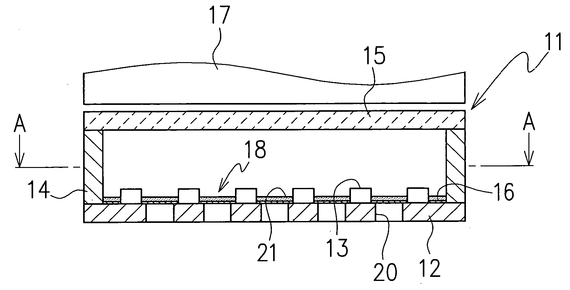
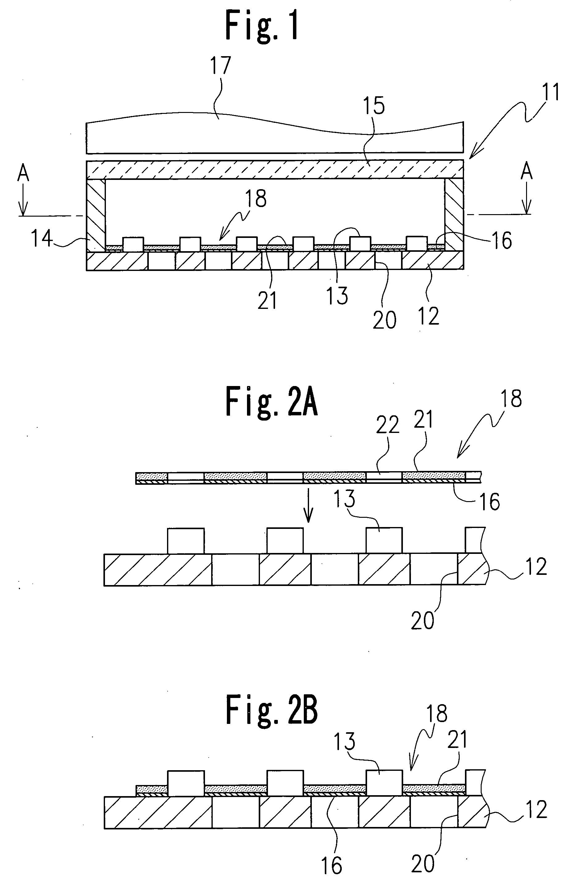
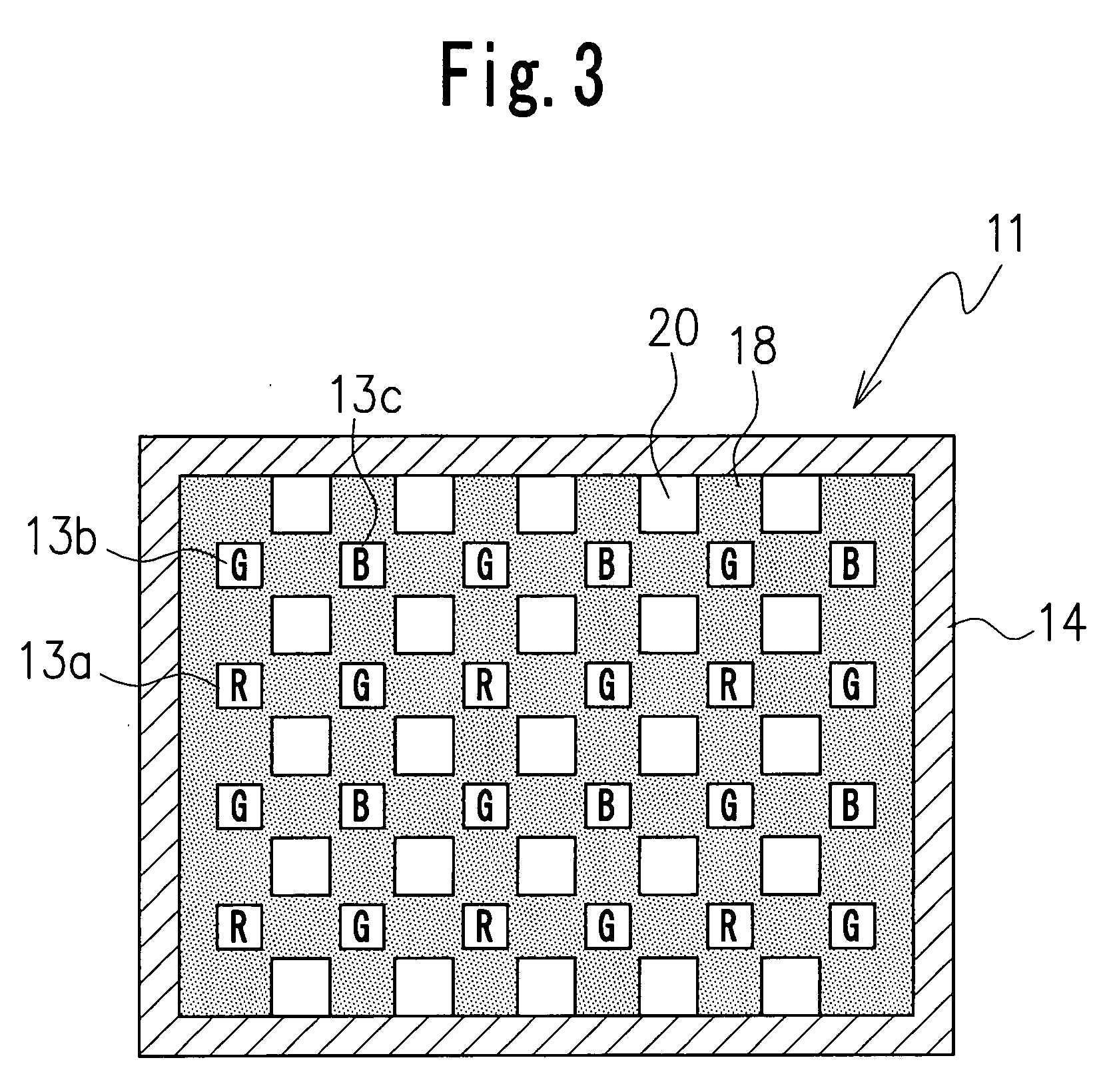
[0020] A structure of a backlight system according to one embodiment of the present invention is shown in FIGS. 1 to 3. The backlight system 11 includes an insulative printed substrate 12 made of glass epoxy resin or the like and having wiring patterns (not shown) formed thereon, a plurality of light sources, for example, LEDs 13, disposed on a surface, for example, an upper surface of the printed board 12 and electrically connected to the wiring patterns, a frame member or reflective frame 14 to surround the plurality of LEDs 13, and a light diffusion member 15 disposed above of the light sources.

[0021] The light diffusion member 15 is mounted on an upper end surface of the reflective frame 14 to face an upper surface or light-emitting surface of each of the LEDs 13. The backlight system 11 is disposed adjacent to a back surface of a liquid crystal display 17 ...


PUM


Abstract

A backlight system including a printed board, a plurality of light sources mounted on a surface of the printed board, a frame member disposed to surround the plurality of light sources, a plurality of through-holes provided in the printed board to reduce weight of the printed board, and a cover member disposed on the printed board to cover the plurality of through-holes, whereby accomplishing great reduction in weight of the printed board without lowering reflection efficiency of light emitted from the light sources and providing a backlight system capable of effectively using for a large liquid crystal display.

Description

CROSS-REFERENCE TO THE RELATED APPLICATION [0001] This application is based on and claims the priority benefit of Japanese Patent Application No. 2004-382176 filed on Dec. 28, 2004, the disclosure of which is incorporated herein by reference in its entirety. BACKGROUND OF THE INVENTION [0002] 1. Field of the Invention [0003] The present invention relates to a backlight system disposed in a back side of a liquid crystal display. [0004] 2. Description of Related Art [0005] Recently, liquid crystal displays each including a backlight system have become widely used in various electronics items such as notebook computers in which optical communication devices are installed, personal digital assistants, mobile phones, liquid crystal televisions or the like. [0006] It is known that this kind of backlight system includes a light-emitting source such as a fluorescent lamp or an LED, and a light diffusion plate configured to uniformly diffuse light emitted from the light-emitting source to il...

Claims


Application Information

Patent Timeline
Patent Type & Authority Applications(United States)
IPC IPC(8): F21V7/04H01L33/60
CPCG02F1/133603H05K1/0274H05K3/281H05K2201/09063H05K2201/10106H05K2201/2054H05K2203/063H05K2203/1394G02F1/1335
Inventor FUKASAWA, KOICHIMIYASHITA, JUNJI
Owner NICHIA CORP
Why Eureka
Try Eureka