Ferrule assembly

a technology of ferrule and fiber, which is applied in the field of optical components, can solve the problems of difficult, if not impossible, to bring the end face of the fiber housed therein into physical contact with the optical path of the mating component, and it is difficult to effect optical coupling with all of the fibers, so as to facilitate precise axial positioning facilitate the effect of reducing the handling of the fiber end face and enhancing the configurability

Inactive Publication Date: 2006-07-06
TYCO ELECTRONICS LOGISTICS AG (CH)
View PDF15 Cites 24 Cited by
  • Summary
  • Abstract
  • Description
  • Claims
  • Application Information

AI Technical Summary

Benefits of technology

[0008] The present invention provides for a ferrule assembly that overcomes the aforementioned problems and offers enhanced configurability. Specifically, the applicants have developed an approach for terminating a fiber in a ferrule which separates the functions of preparing the fiber's end face for optical coupling and positioning the fiber within the ferrule. This is a departure from conventional approaches in which the two functions are performed in a single polishing step. By treating the functions individually, the fiber end face can be prepared independent of the ferrule, thereby eliminating the need to polish the ferrule / fiber assembly. Generally, it is preferred that the fiber be cleaved after it is disposed in the ferrule to minimize handling of the fiber end face which can blemish or otherwise optically degrade the end face. Furthermore, since the ferrule assembly is not subject to polishing, the axial position of the end face relative to the ferrule can be addressed independently from its preparation. This facilitates precise axial positioning of the fiber end face relative to the ferrule. Generally, it is preferred to have the fiber end face protrude from the ferrule to enhance its ability to make physical contact for optical coupling.

Problems solved by technology

An unpolished ferrule has a geometry and anomalies on its mating face which make it difficult, if not impossible, to bring the end face of fiber housed therein into physical contact with the optical path of the mating component.
In addition, when multiple fibers are affixed to an unpolished ferrule, the positions of the fiber ends tend to vary along the mating axis, thereby making it difficult to effect optical coupling with all of the fibers.
Unfortunately, to minimize the variances and shape the ferrule, polishing must be performed to exacting standards.
Polishing therefore tends to be costly and prone to reworking and waste, thereby lowering yields.
The problems associated with polishing the ferrule are exasperated in multi-fiber ferrules which are more complicated to polish.

Method used


Image

  • Ferrule assembly
  • Ferrule assembly
  • Ferrule assembly

Examples


Embodiment Construction

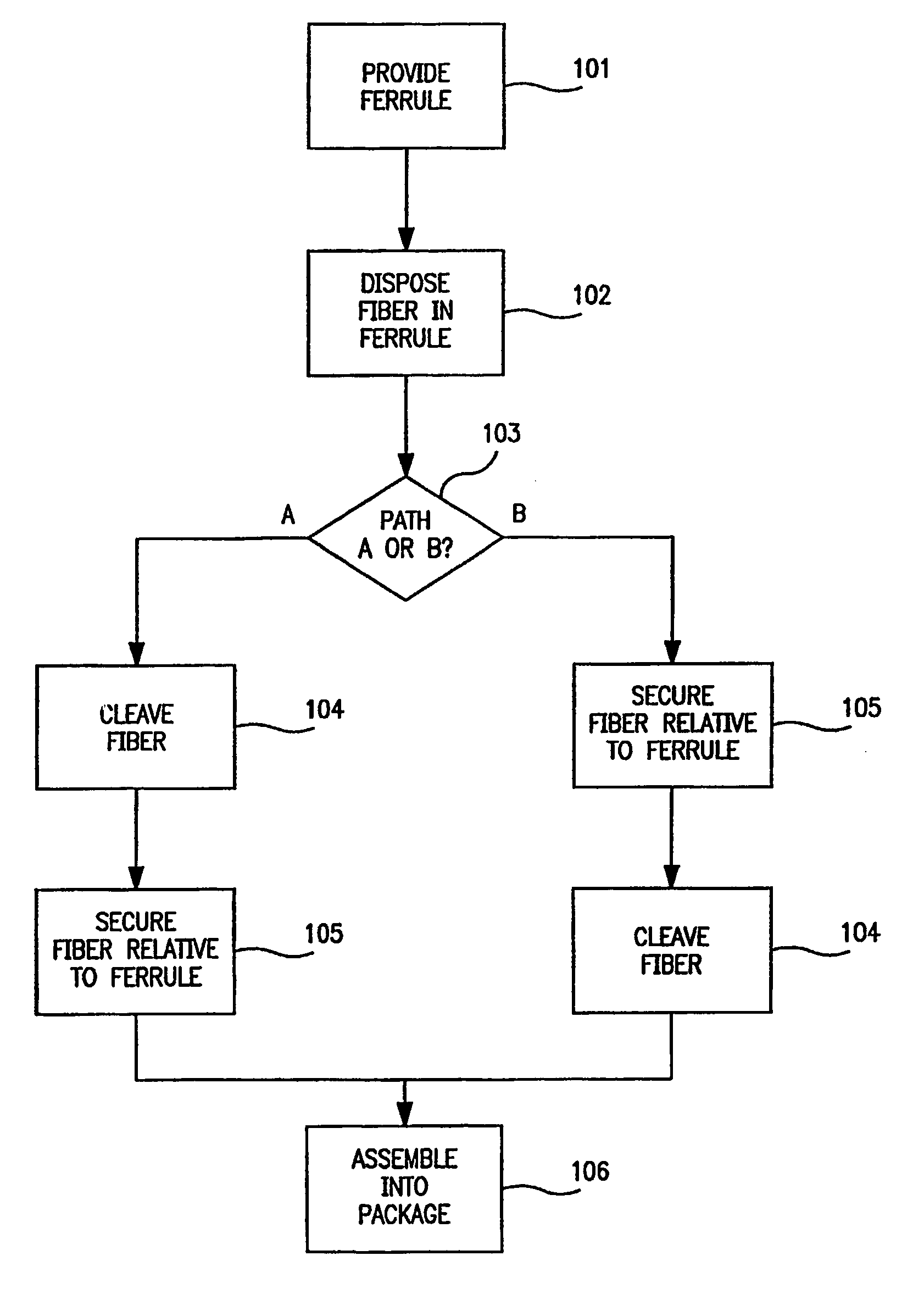
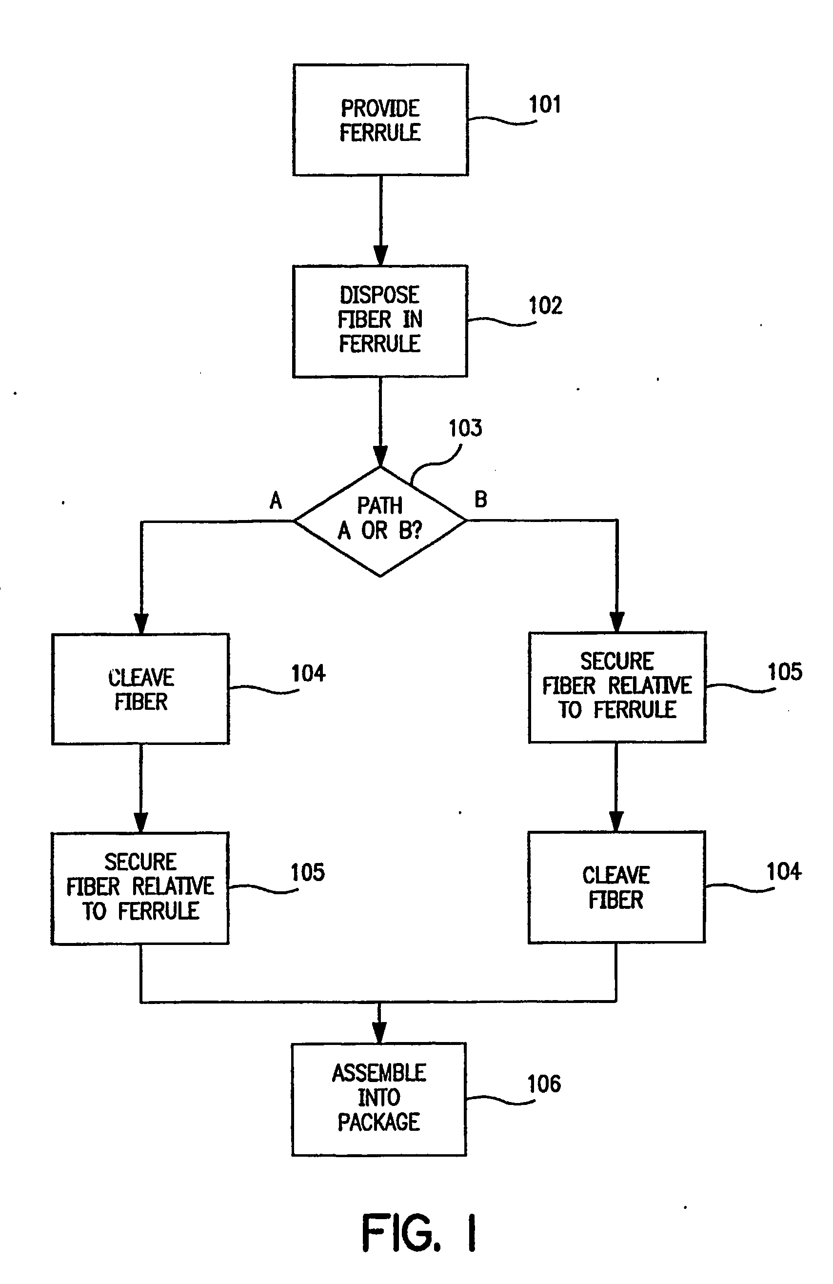
[0021] Referring to FIG. 1, a flow chart 100 depicting an overview of a preferred method of the present invention is shown. In step 101, a ferrule for an optical connector is provided. The ferrule has one or more pathways to receive fibers therein. In step 102, one or more fibers are positioned in the pathways of the ferrule such that a portion of each fiber extends beyond the end face of the ferrule. At this point, a decision block 103 is reached in which the process of the present invention follows a path A or path B. If path A is followed, the process proceeds to step 104 in which the fibers are cleaved. Cleaving the fibers can be performed using any traditional technique, although laser cleaving is preferred. Once cleaved, the process proceeds to step 105, in which the position of the fibers relative to the ferrule is secured, thereby forming the ferrule assembly. As used herein, the term “ferrule assembly” refers to a ferrule having one or more fibers terminated in it. At this ...


PUM

PropertyMeasurementUnit
diameteraaaaaaaaaa
diameteraaaaaaaaaa
diameteraaaaaaaaaa

Abstract

A process for preparing terminated fibers comprising: (a) positioning at least one fiber in a ferrule such that a portion of the fiber extends beyond the mating face of the ferrule; (b) affixing the fiber relative to the ferrule; and (c) cleaving the portion of the fiber.

Description

REFERENCE TO RELATED APPLICATION [0001] This application claims priority to U.S. Provisional Application No. 60 / 0377267, filed May 2, 2002 and hereby incorporated by reference.FIELD OF INVENTION [0002] The present invention relates generally to an optical component, and, more specifically, to a ferrule-containing optical connector. BACKGROUND OF INVENTION [0003] Optical fiber connectors are an essential part of substantially all optical fiber communication systems. For instance, optical connectors are used to join segments of fiber into longer lengths, to connect fiber to active devices such as radiation sources, detectors and repeaters, and to connect fiber to passive devices such as switches and attenuators. The principal function of an optical fiber connector is to hold a fiber end such that the core of the fiber is axially aligned with the optical path of the component to which the connector is mated (e.g., another fiber, a planar waveguide, or an opto-electric device). This way...

Claims


Application Information

Patent Timeline
Patent Type & Authority Applications(United States)
IPC IPC(8): G02B6/36G02B6/25G02B6/32G02B6/38G02B6/42
CPCG02B6/25G02B6/327G02B6/3818G02B6/3833G02B6/3855G02B6/4204
Inventor MANNING, RANDY MARSHALLHULTRMANS, ANTONIUSVAN GEFFEN, SJOERDBAECHTLE, DAVID
Owner TYCO ELECTRONICS LOGISTICS AG (CH)
Why Eureka
Try Eureka