Television camera

a technology for television cameras and frames, applied in the field of television cameras, can solve the problems of inability to promote imaging cost reduction, inability to bring into a photographing site, and unsuitable portability of frame rate converting devices, so as to achieve the effect of widening the width of an effect obtained by special photographing, increasing the size and weight, and increasing the effect of siz

Active Publication Date: 2006-07-06
PANASONIC INTELLECTUAL PROPERTY MANAGEMENT CO LTD
View PDF3 Cites 67 Cited by
  • Summary
  • Abstract
  • Description
  • Claims
  • Application Information

AI Technical Summary

Benefits of technology

[0013] The second video signal outputted from the memory device is thereby given a time-image effect, which allows the video signal with the time contraction effect on the image to be outputted by means of the television camera alone. Further, the television camera, which is additionally provided with only the memory device and the control devices for controlling the read and write with respect to the memory device, does not incur a large increase in size (increase in weight) and cost.
[0014] In a modification example of the television camera according to the present invention, the first video signal generated by the image pickup device includes a video signal generated in a temporally at-random intermittent imaging. According to the constitution, a width of an effect obtained by a special photographing can be widened.
[0015] In another modification example of the television camera according to the present invention, a recorder for recording the second video signal is further included. According to the constitution, the second video signal with a special effect can be photographed and memorized at the same time, which is more convenient in the photographing.
[0016] In still another modification example of the television camera according to the present invention, a display device for displaying the second video signal outputted from the memory device is further included. According to the constitution, the time-image effect given to the second video signal can be confirmed immediately after the photographing when the display device is visually checked.
[0017] In still another modification example of the television camera according to the present invention, a converting device for converting the first video signal into the standard video signal having the standard frame rate determined by the output standard format of the television camera, a selecting device for selecting from the second video signal outputted from the memory device and the standard video signal outputted from the converting device, and a display device for displaying an output of the selecting unit are further included. According to the constitution, an image of the second video signal with the time-image effect and an image of the first video signal which is a real-time image with no time-image effect can be selected by the selecting device and accordingly displayed on the display device. As a result, the real-time image and the image with the time-image effect can be compared to each other on the television camera.

Problems solved by technology

However, the frame rate converting device has a size and a mass unsuitable for portability and therefore cannot be brought into a photographing site.
Due to the disadvantage, image data obtained by the image pickup (video tape) has to be brought into a location where the frame rate converting device is installed so that the time elongation / contraction effect can be confirmed through reproducing and converting processes implemented by the frame rate converting device.
Such an inconvenience is a barrier to the reduction of a time length required for the photographing (speedier photographing).
Further, an imaging cost reduction cannot be promoted because the frame rate converting device, which is costly, is indispensable for obtaining the time elongation / contraction effect on the image.

Method used


Image

  • Television camera
  • Television camera
  • Television camera

Examples


Embodiment Construction

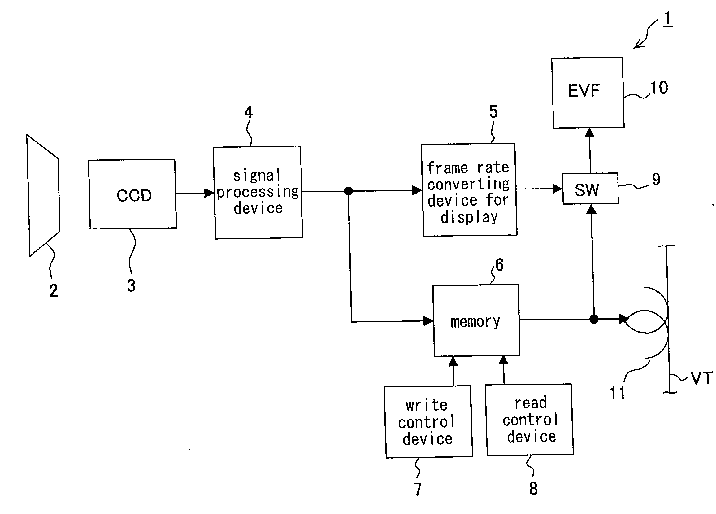
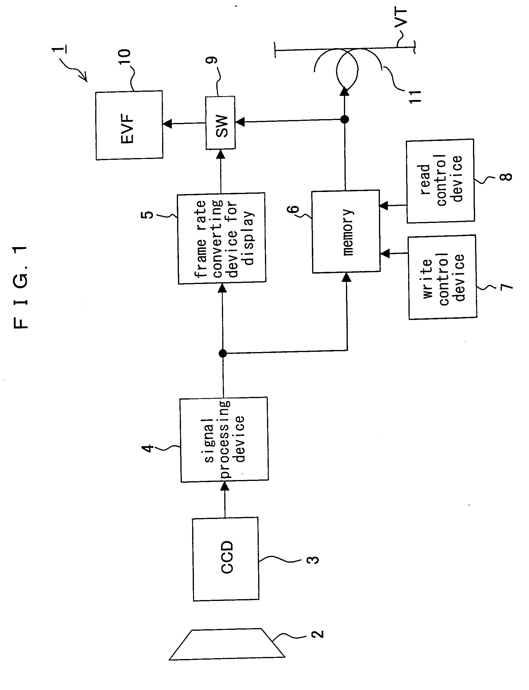
[0031] Before a preferred embodiment of the present invention is described, an image processing operation in an image processing system in which a frame rate converting device and a television camera are combined is described referring to FIGS. 12 and 13. A television camera according to the present invention results from the improvement of the image processing operation in the foregoing image processing system. In the image processing system, as the television camera is used a television camera in which a recording device is integrally incorporated having an image pickup device (CCD device or the like) capable of optionally setting a frame rate.

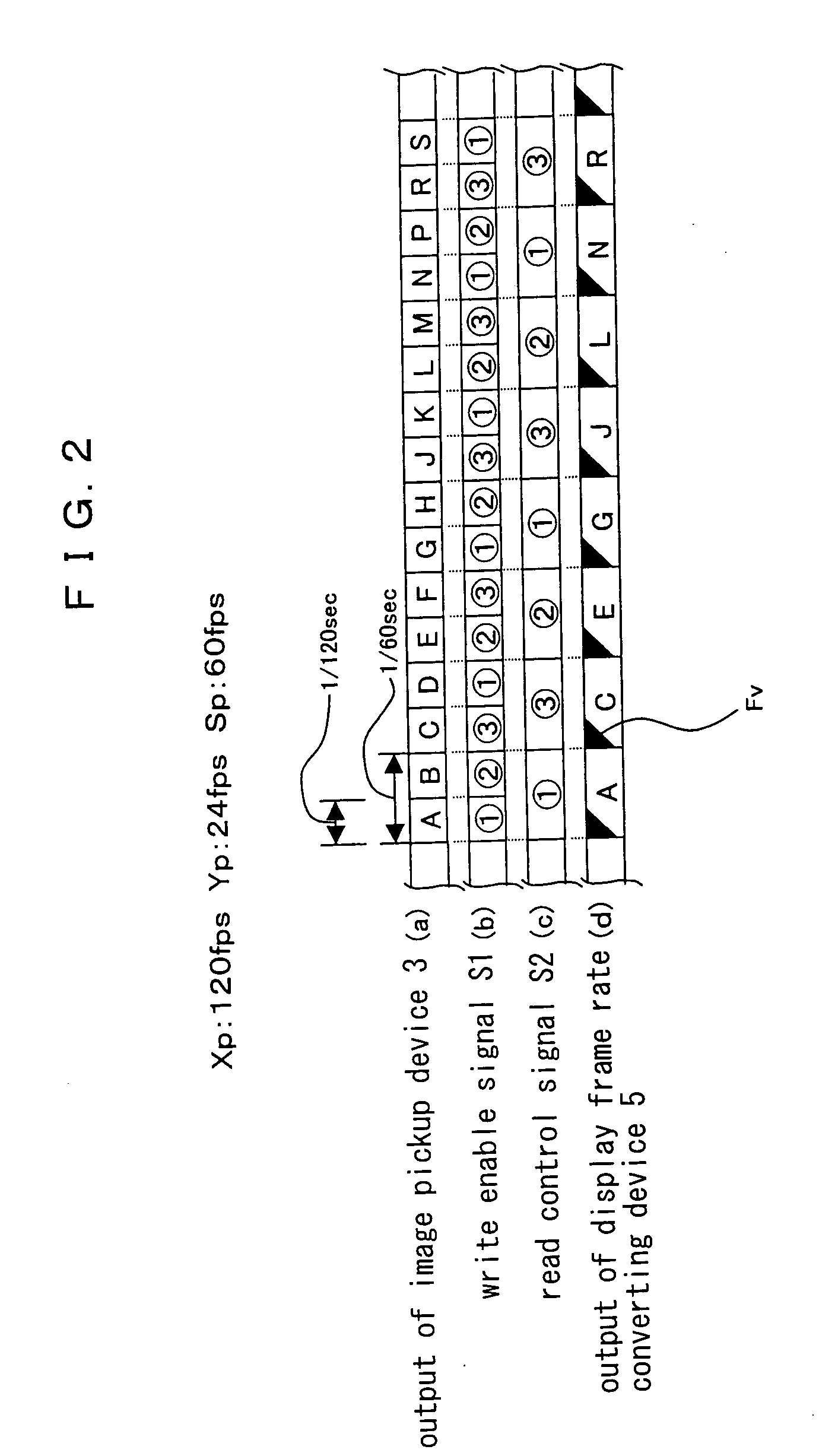
[0032] A processing step shown in FIG. 12 is described. A first video signal picked up at a frame rate of 60 fps in the image pickup device (see FIG. 12(a)) is recorded on a videotape in the television camera as the fist video signal of 60 pfs without any change (see FIG. 12(b)). Then, the videotape is installed in a reproducing unit of the...


PUM


Abstract

A first video signal having a first frame rate optionally settable is generated by an image pickup device, and the first video signal is memorized in a memory and outputted from the memory. A write control device controls the write of the first video signal with respect to the memory, and a read control device controls the read of the video signal with respect to the memory. The write control device writes respective first frame data constituting the first video signal in the memory in each cycle determined by the first frame rate of the first video signal. The read control device reads the first frame data as a second video signal. The second video signal is formed from sequentially arranging the first frame data in a partially duplicating manner in a standard video signal having a standard frame rate based on a determined arrangement rule. The predetermined arrangement rule is an arrangement rule employed when respective frame data constituting a video signal having a second frame rate equal to or lower than the standard frame rate are arranged in a duplicating manner in the standard video signal. In the foregoing manner, an time elongation/contraction effect on an image can be speedily and inexpensively obtained.

Description

FIELD OF THE INVENTION [0001] The present invention relates to a television camera capable of picking up a video signal based on an optionally settable frame rate. BACKGROUND TECHNOLOGY [0002] A television camera in which a recording device is integrally incorporated comprising an image pickup device (CCD device or the like) capable of optionally setting a frame rate is conventionally available. Further, an image processing system in which the television camera and a frame rate converting device are combined with each other so that a complicated time elongation / contraction effect can be imparted to an outputted image is also conventionally available. An example of the conventional image processing system is recited in P5-P10 and FIG. 1 of No. 2000-152569 of the Publication of the Unexamined Japanese Patent Applications. [0003] In the conventional image processing system, the time elongation / contraction effect on the image cannot be ultimately confirmed until an output of the frame r...

Claims


Application Information

Patent Timeline
Patent Type & Authority Applications(United States)
IPC IPC(8): H04N5/76H04N5/232H04N5/225H04N5/77H04N5/92H04N7/01
CPCH04N5/772H04N7/0105H04N25/71G11B20/10527G11B2020/10592H04N5/05
Inventor TAKEMOTO, SHINJIFUSE, SHOICHIMOTODA, KAZUMANODA, AKIYUKI
Owner PANASONIC INTELLECTUAL PROPERTY MANAGEMENT CO LTD
Why Eureka
Try Eureka