Systems and methods for facilitating wireless communication between various components of a distributed system

a distributed system and wireless communication technology, applied in the field of wireless networks, can solve the problems of high cost of communication cables, high cost of cables themselves, and inability to meet the needs of users, and achieve the effect of reducing the amount of power required for transmission

Active Publication Date: 2006-07-06
AIR LIQUIDE ELECTRONICS US LP
View PDF9 Cites 11 Cited by
  • Summary
  • Abstract
  • Description
  • Claims
  • Application Information

AI Technical Summary

Benefits of technology

[0011] Although communications typically flow directly to the central control module, in some embodiments, the system may include local control modules that are connected to one or more components that act as an intermediate relay information from the components to and from the central control module. Typically, the individual wireless modules on each component operate as clients that interact with the central control module. However, in some embodiments, the wireless modules may operate as both clients and servers to other wireless modules on other components. This allows the wireless modules to pass data from one component to the next and ultimately back to the central control module. This method provides a redundant path for the flow of data since the components can route the data in many ways. Also, the amount of power required for transmission can be reduced since the component need only communicate with its nearest neighbors and not directly with the central control module.

Problems solved by technology

The use of communication cables is expensive in both design and in implementation.
The cables themselves are also expensive, with a good portion of the cost residing in the connectors.
The connectors are also problematic in terms of reliability both during maintenance and in normal operation.
In addition, not all of the various devices have the same type of communication medium or protocol.
All of these factors conspire to drive the cost of the system up and the reliability down, particularly since many of the communications are point-to-point serial.

Method used


Image

  • Systems and methods for facilitating wireless communication between various components of a distributed system
  • Systems and methods for facilitating wireless communication between various components of a distributed system
  • Systems and methods for facilitating wireless communication between various components of a distributed system

Examples


Embodiment Construction

[0019] The present inventions now will be described more fully hereinafter with reference to the accompanying drawings, in which some, but not all embodiments of the invention are shown. Indeed, these inventions may be embodied in many different forms and should not be construed as limited to the embodiments set forth herein. Like reference numerals are used to refer to like elements throughout the drawings.

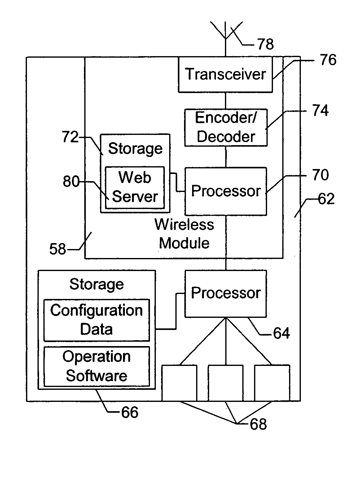
[0020] As discussed above and provided in more detail below, the systems and methods of the present invention provide a wireless network for connecting the various components located on manufacturing equipment, and the like. It is contemplated that the systems and methods of the present invention may be incorporated into any machinery or equipment that comprises a plurality of distributed components, where communication with the various components is desired. In these embodiments, the cables usually connecting the various components are replaced by wireless modules located on ea...


PUM


Abstract

The present invention provides systems and methods for facilitating communications between various components of distributed system. Specifically, the systems and methods of the present invention provide a wireless network for linking the various components of manufacturing equipment or manufacturing systems to one or more central control devices. Each component of the manufacturing equipment and the central control devices include a wireless module for handling communications between the components and the control devices. In some embodiments, one or more of the components may act as a server for other components in the network. In some embodiments, multiple data channels are used for communication between the components and the central control devices.

Description

BACKGROUND OF THE INVENTION [0001] 1. Field of the Invention [0002] The present invention relates generally to a wireless network and more particularly to a wireless network for communicating information and commands between the various components of manufacturing equipment or manufacturing systems. [0003] 2. Description of Related Art [0004] Many of today's manufacturing equipment includes a wide variety or sensors and actuators that respectively provide data concerning a manufacturing process and control various components used in the manufacturing process. Theses sensors and actuators are connected to local controllers that are in turn, connected to a central control system. In some instances, the sensors and actuators are connected directly to the central control system. Importantly, in most conventional manufacturing equipment, the various components communicate normally using a physical connection for communications, such as a twisted pair of wires, or other cabling. The use o...

Claims


Application Information

Patent Timeline
Patent Type & Authority Applications(United States)
IPC IPC(8): H04Q7/20H04W84/00
CPCG05B19/4186G05B2219/31162G05B2219/45031H04W84/00Y02P90/02
Inventor BOGER, MICHAELRUSSELL, THOMASMARINI, LARRY
Owner AIR LIQUIDE ELECTRONICS US LP
Why Eureka
Try Eureka