Bone fastener assembly for bone retention apparatus

a bone retention and assembly technology, applied in the field of apparatus, can solve the problems of difficult installation, preventing a secure connection between the components of the bone alignment system, and difficult plate placement between two or more rigid screws, and achieve the effect of convenient attachment to the applian

Active Publication Date: 2006-07-06
BRAY ROBERT S JR DR
View PDF72 Cites 83 Cited by
  • Summary
  • Abstract
  • Description
  • Claims
  • Application Information

AI Technical Summary

Benefits of technology

[0013] According to all the foregoing aspects, the combined rotational and translational degrees of freedom provided by t...

Problems solved by technology

The secure placement of a rod with a rigid bone fastener, whether or not a coupling member is used, or the placement of a plate between two or more rigid screws is difficult for a variety of reasons.
For example, the displacement or angulation of the vertebrae may be such that the rigidity of the bone fastener and/or coupling member, where a coupling member is used, prevents a secure connection from being made am...

Method used


Image

  • Bone fastener assembly for bone retention apparatus
  • Bone fastener assembly for bone retention apparatus
  • Bone fastener assembly for bone retention apparatus

Examples


Embodiment Construction

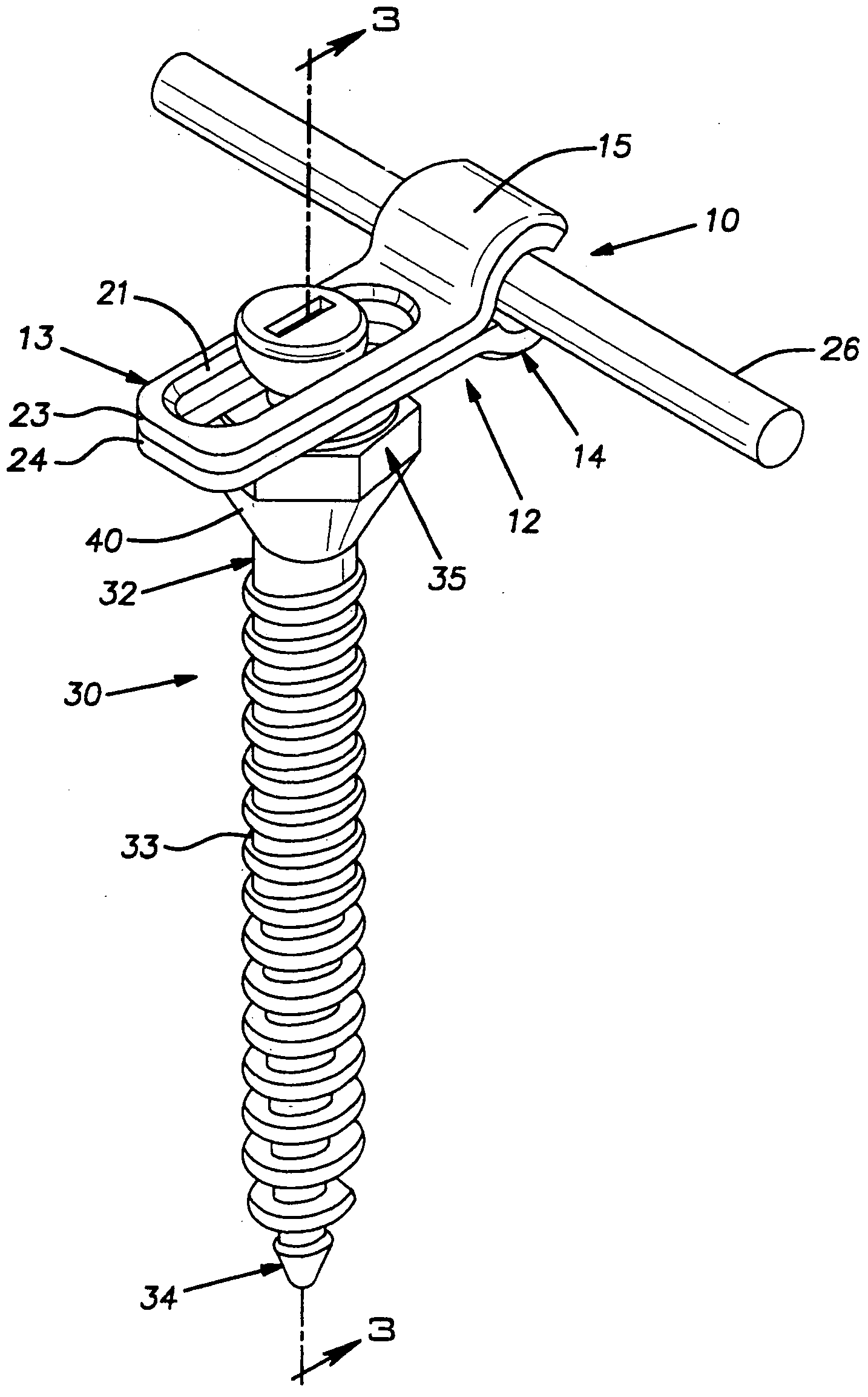
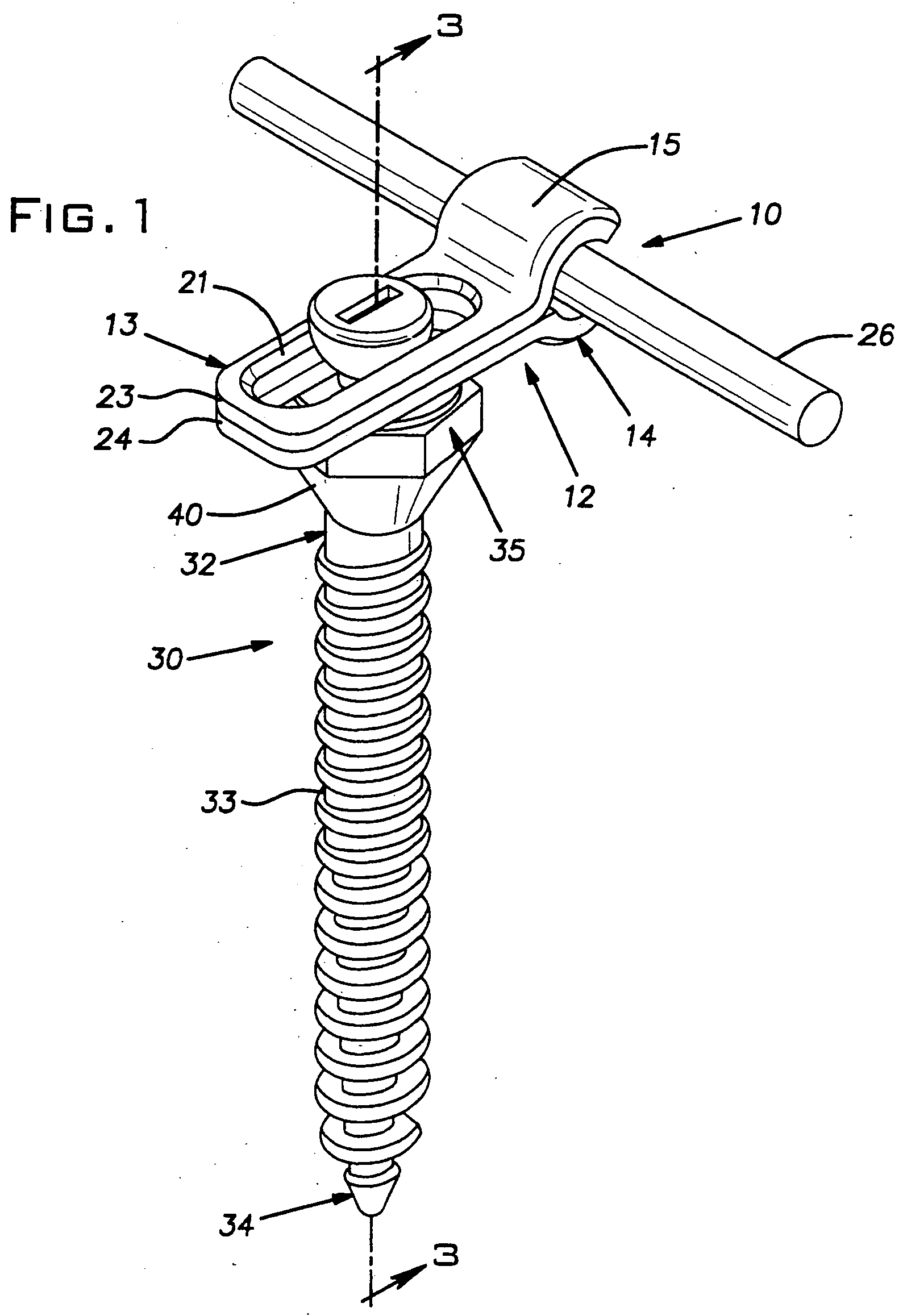
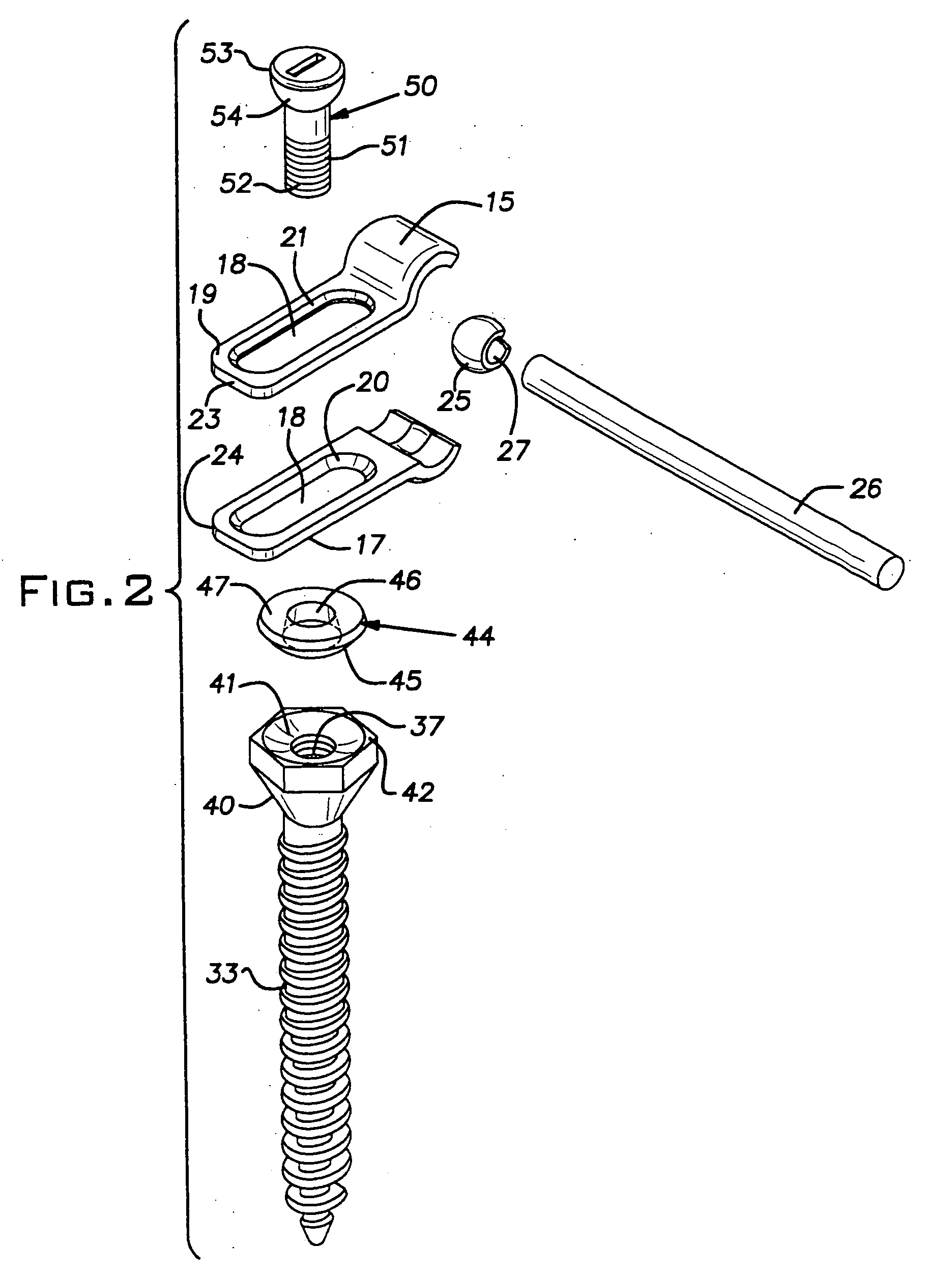
[0018] Referring first to FIG. 1 of the drawings, there is shown in an assembled state apparatus for use in retaining bone bodies, such as spinal vertebrae, in a desired spatial relationship. The apparatus includes an appliance, indicated generally at 10, for aligning bone bodies, and a bone fastener assembly, indicated generally at 30, for fastening the appliance to one of the bone bodies.

[0019] In the embodiment of the invention shown in FIG. 1, the appliance comprises a coupling member, indicated generally at 12, and an elongated member or fixation rod 26. The coupling member 12 has a first portion, indicated generally at 13, that is secured to the bone fastener assembly 30 and a second portion, indicated generally at 14, that is connected to the rod 26. Typically, for the purpose of stabilizing the vertebrae in a spinal column so that the vertebrae are retained in a desired spatial relationship, a respective coupling member 12 and an associated bone fastener assembly 30 secured...


PUM


Abstract

A bone fastener assembly, comprising a bone fastener, an adjusting member and a securing fastener is provided for fastening an appliance to a bone body so that a plurality of the bone fastener assemblies and the appliance constitute an apparatus that acts to retain a plurality of bone bodies in a desired spatial relationship. Each bone fastener has an attaching portion for attaching the bone fastener to a bone or bone part, a supporting portion for supporting the adjusting member for universal movement relative to the supporting portion, and a securing portion for securing the bone fastener to the securing fastener. The securing fastener has a first end that passes through an aperture in the appliance and an opening in the adjusting member and is secured to the securing portion of the bone fastener. A second end of the securing fastener has a bearing surface that adjustably bears against the appliance in opposition to an engaging surface of the adjusting member that engages the appliance.

Description

FIELD OF THE INVENTION [0001] The present invention relates to apparatuses that have utility in connection with the retention of bone bodies in a desired spatial relationship. More particularly, the invention concerns a pedicle screw assembly for an appliance that maintains a desired spatial relationship among the vertebrae of a spine. BACKGROUND OF THE INVENTION [0002] A variety of devices are known for the fixation, internally or otherwise, of bone bodies in humans and animals. In the case of the internal fixation of the vertebrae of a spinal column, so that the vertebrae are maintained in a desired spatial relationship with respect to one another, the devices often include pedicle screw, or bone fastener, assemblies. These assemblies include a pedicle screw, or bone fastener, that is anchored, typically by a threaded arrangement, into the pedicle of each of the vertebrae that are to be maintained in a desired spatial relationship. One or more appliances such as longitudinal suppo...

Claims


Application Information

Patent Timeline
IPC IPC(8): A61F2/30
CPCA61B17/7037A61B17/704A61B17/7041
Inventor BRAY, ROBERT S.
Owner BRAY ROBERT S JR DR
Why Eureka
Try Eureka