
Distributed database system

a database system and database technology, applied in the field of distributed database systems, can solve the problems of limiting usage, affecting the stability of the database, and unable to maintain consistency between the updated contents and the contents before the backup

Inactive Publication Date: 2006-07-06
NISHIYAMA SHUHEI
View PDF4 Cites 33 Cited by
  • Summary
  • Abstract
  • Description
  • Claims
  • Application Information

AI Technical Summary

Benefits of technology

[0020] This enables easy caching of a database object to a computer, thereby resolving the deficiency.
[0042] This enables backup without stoppage of a database, thereby resolving a deficiency.

Problems solved by technology

However, the two-phase commit causes a decline in performance, and a solution thereof has been suggested by Japanese Patent Publication No. 2001-306380, page 2-3.
Moreover, replication is a technology for resolving the deficiency that the two-phase commit takes too long time to be put into practical use.
Therefore, since the update is executed by periodically referring to the update information from a server, which caches, it takes several minutes to synchronize the original table with the copy, thereby limiting the usage thereof.
In the conventional backup of a database, it is assumed that low-speed memory medium is used as a backup medium, and if backup is executed without stopping the database, it becomes impossible to maintain consistency between the updated contents and the contents before the backup.
However, two-phase commit and replication require complex procedure to incorporate one computer into the distributed database system.
This makes it difficult to distribute data.
However, in these computers, word processor and spreadsheet processing program, or processing tool of presentation etc. are operated only in the daytime, therefore, CPU, memory, and disk have surplus capacity, and are not utilized effectively.
Moreover, this is not limited to a corporate environment, for example, in case of multiple occupancy dwellings with constantly-connected internet, CPU, memory, and disk thereof are not utilized effectively.
Furthermore, in cases where data is distributed, it becomes difficult to stop a database.
This makes it impossible to use the conventional backup method of the database.

Method used


Image

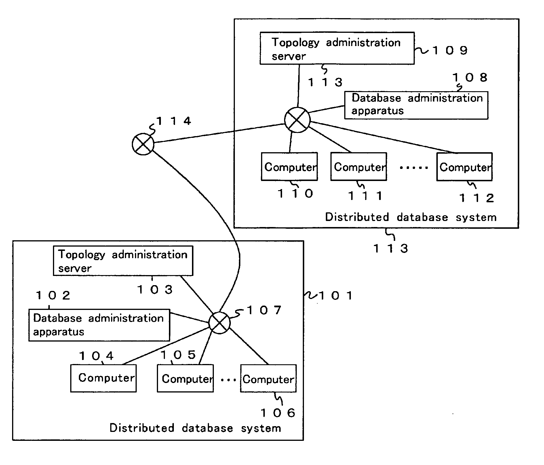
  • Distributed database system
  • Distributed database system
  • Distributed database system

Examples


first embodiment

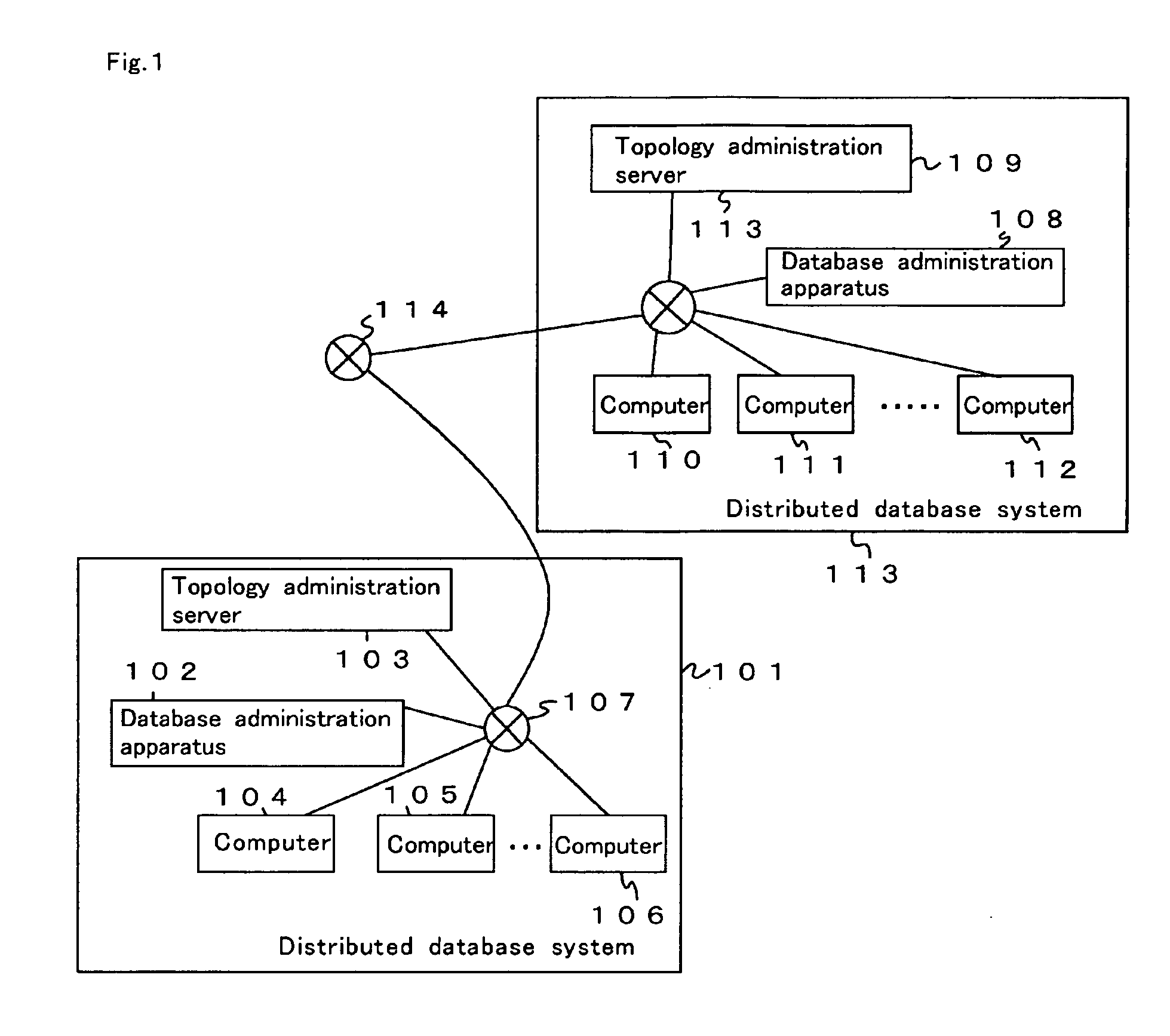
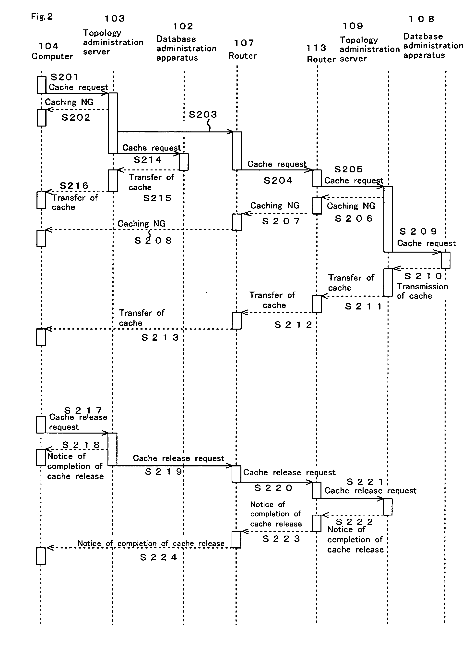
[0131] According to the distributed database system of the first embodiment, if the computer has a function of transmitting the cache request and of caching the returned database object, it becomes possible to participate in the distributed database system, thereby enabling easy distribution of data. Moreover, since a copy of the database object is cached by the computer, even if the interruption occurs in the database administration apparatus, it becomes able to recover by using the cache in the computer. Furthermore, the database object is cached in the computer, thereby enabling multiplexing (mirroring to a plurality of computer apparatuses physically existing in the other place) of the database object. This multiplexing enables continuation of the system without stopping the service of the entire system under a situation that stoppage of the database administration apparatus is required because of check or replacement, etc.

second embodiment

[0132] In the present invention, the distributed database system, in which computation is performed referring to a database object cached in a computer, is provided. Therefore, grid-computing is implemented.

[0133]FIG. 15 is a functional block diagram of the computer 403 of the distributed database system of the second embodiment. The computer of the second embodiment is the computer of the first embodiment and further comprises the receiver for the program 1501.

[0134] The “receiver for the program”1501 receives a program for computation referring to a database object cached by the caching unit for database object 1103. The program may be received by using, for example, ftp. Moreover, the external server may transmit or receive a program regularly or irregularly. Note that, the external server may exist within or outside of the distributed database system. Moreover, the program may be stored in the medium such as an optical disk, and may be received by reading the medium.

[0135] The...

third embodiment

[0137] the present invention provides the distributed database system comprising a computer, which transmits a cache request based on load.

[0138]FIG. 16 is a functional block diagram of the distributed database system of the third embodiment. The computer 403 of the third embodiment further comprises a detection unit for computational load.

[0139] The “detection unit for computational load”1601 detects the computational load of computer 403. Moreover, examples of “computational load” include: CPU usage, data occupancy of a magnetic disk, and communication status (e.g. number of discarded packets, number of transmitted or received packets per a predetermined time)

[0140] In the third embodiment, the transmitter for cache request 1101 transmits a cache request based on the computational load detected by the detection unit for computational load 1601. For example, in cases where the memory usage (percentage) is below a predetermined value, or in cases where the CPU usage is below a pre...


PUM


Abstract

Disclosed is a distributed database system, which effectively utilizes surplus resources of a plurality of computers. For this, a topology administration server device correlates an identifier identifying a database object administered by a database administration device with an identifier identifying the database administration apparatus. When a plurality of computers transmit a cache request including an identifier identifying a database object to the topology administration server device so as to cache the database object, the topology administration server device transfers the cache request to the database administration device so that the database object is transmitted to a computer and cached there. It is also possible to operate a program executing calculation in a computer while referencing the database object cached.

Description

BACKGROUND OF THE INVENTION [0001] 1. Field of the Invention The present invention relates to a distributed database system and a grid computing system utilizing the distributed database system. [0002] 2. Description of the Prior Art [0003] In a typical prior art commercialized relational database system, the data distribution is implemented by two-phase commit and by replication; a hard-disk is utilized as storage medium of the database, so that the database stops when backup is performed. [0004] In the two-phase commit, when a change of the value of a cell or a deletion of the column of the cell in a referred table is performed among cells of the table which are regulated and have reference / referenced relationships, (assuming that the reference tables are distributed into a plurality of host computers) it is necessary to avoid causing a reference cell to refer to a non-existent referenced cell. Therefore, once a check is executed on the referenced table on the host computer, when ...

Claims


Application Information

Patent Timeline
Patent Type & Authority Applications(United States)
IPC IPC(8): G06F17/30G06F12/00H04L12/24
CPCG06F17/3048G06F17/30575H04L41/024H04L41/0896H04L41/12G06F16/27G06F16/24552
Inventor NISHIYAMA, SHUHEI
Owner NISHIYAMA SHUHEI
Learn More