Device for determing at least one parameter of a medium flowing inside a conduit

a technology of at least one parameter and a conduit, which is applied in the direction of electric control, instruments, combustion air/fuel air treatment, etc., can solve the problems of reducing the accuracy of the measurement results, and reducing the signal noise. , to achieve the effect of improving the flow quality

Inactive Publication Date: 2006-07-13
ROBERT BOSCH GMBH
View PDF7 Cites 9 Cited by
  • Summary
  • Abstract
  • Description
  • Claims
  • Application Information

AI Technical Summary

Benefits of technology

[0003] In contrast, a separation of the flow in the region of the bent section of the measuring channel is prevented by the device according to the present invention for determining at least one parameter of a medium flowing in a line. This may be achieved via a projection that may project into the measuring channel, and that may be located downstream from the inlet and upstream from the measuring element, as viewed in the measuring channel flow direction. The projection may direct the flow and counteract a separation of the flow of the partial stream of medium from the channel walls of the measuring channel. The flow may be directed around the bend by the projection with little or no separation, which may improve the flow quality at the sensor element and reduce the signal noise.

Problems solved by technology

A disadvantage of this is that the stream may separate in the area of the bend and produce zones having a slower flow velocity, or even a backflow.
Since the bent section transitions into a further section equipped with the measuring element, the separation of the flow upstream from the sensor element has an unfavorable effect on the flow conditions at the sensor element, which can result in increased signal noise in the sensor signal.
The resultant change in the sensor signal may result in a disadvantageous deviation of the measured results from the values that are actually present.

Method used


Image

  • Device for determing at least one parameter of a medium flowing inside a conduit
  • Device for determing at least one parameter of a medium flowing inside a conduit
  • Device for determing at least one parameter of a medium flowing inside a conduit

Examples


Embodiment Construction

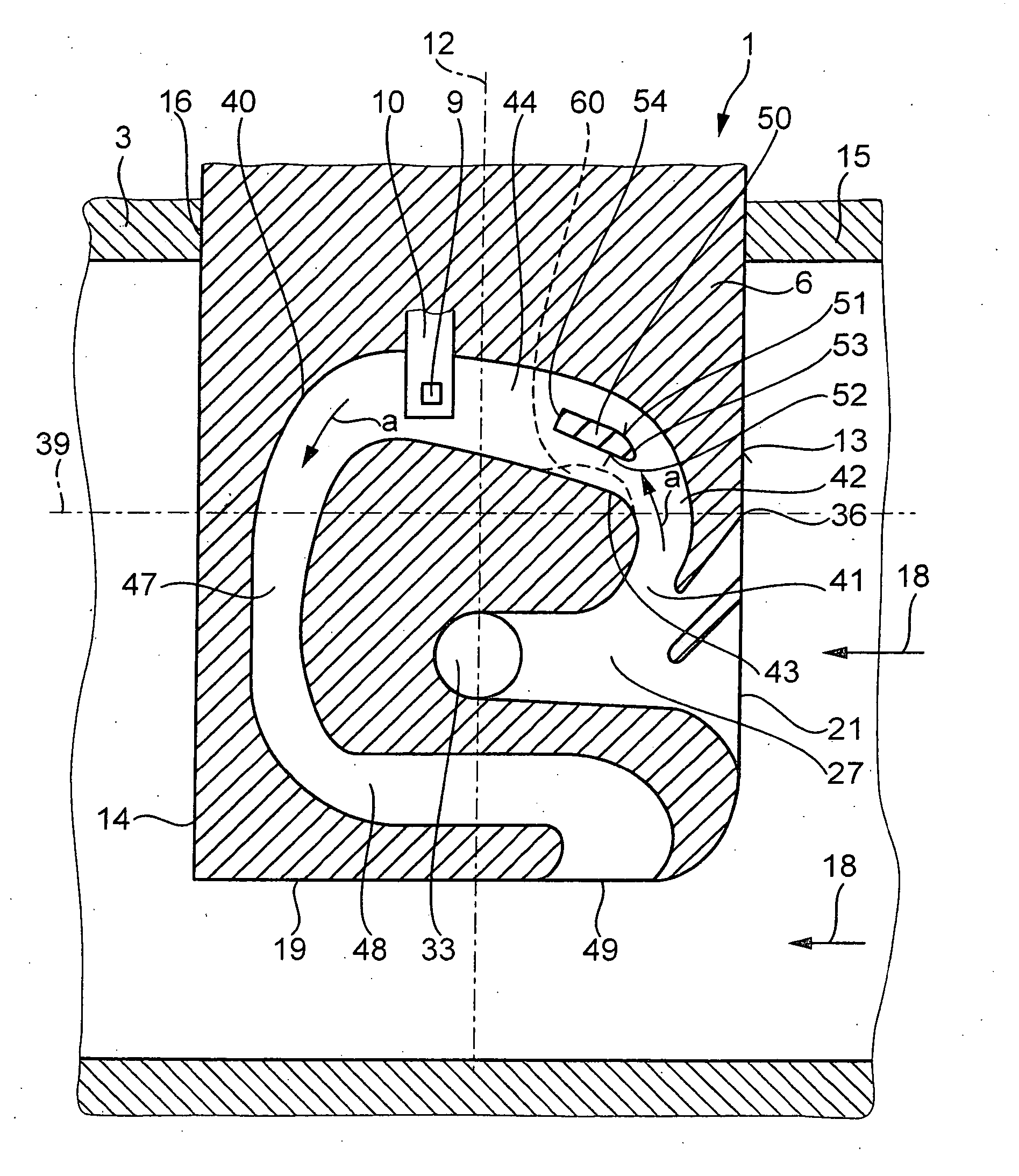
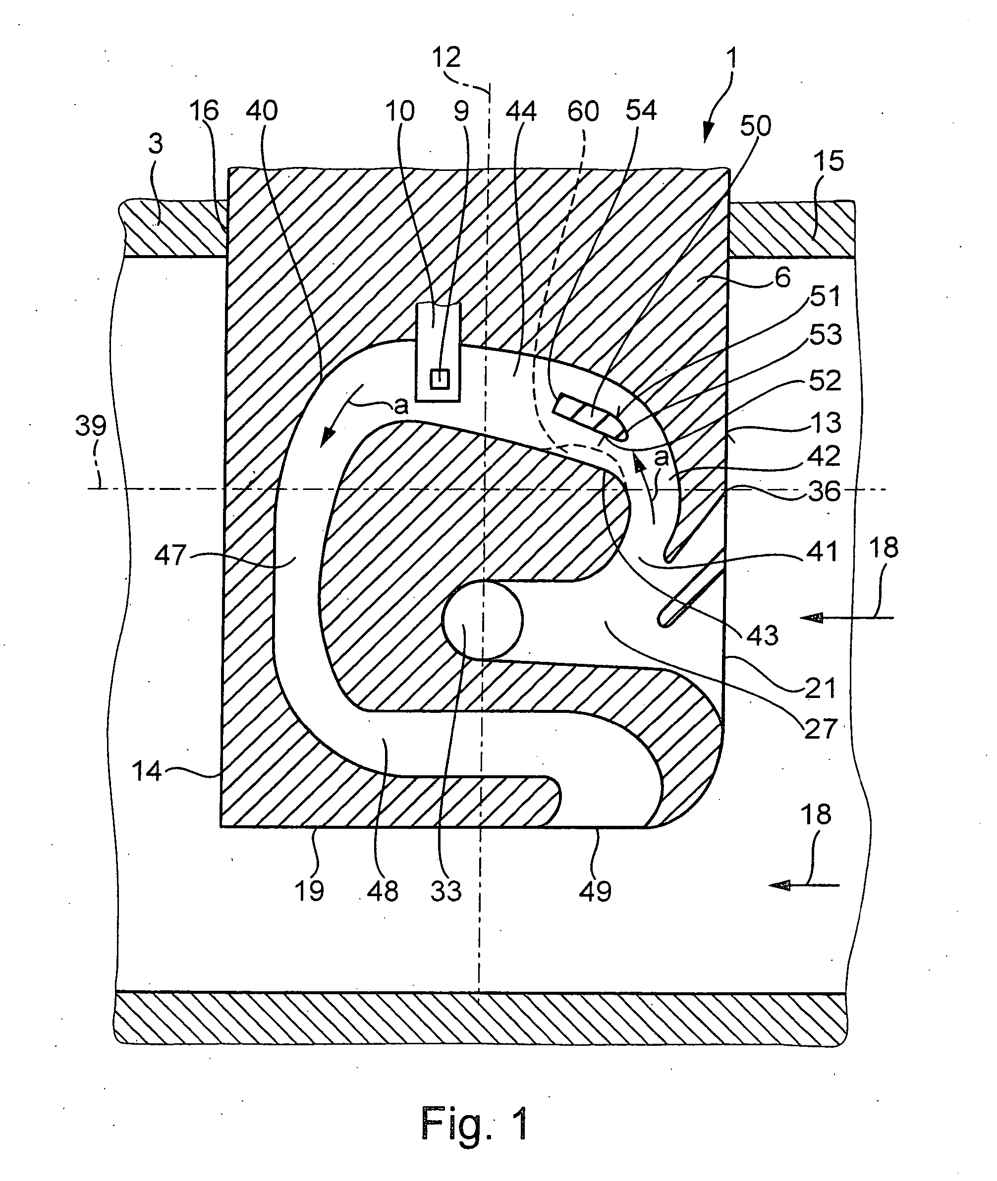
[0008]FIG. 1 shows a section of a line 3 through which a medium may flow in a main flow direction 18. The line may be an intake manifold of an internal combustion engine, for example. The medium may be, e.g., the air that is flowing in the intake manifold toward the internal combustion engine. A device 1 for determining a parameter of the medium flowing in line 3 may be positioned in line 3 in such a manner that a part 6 of this device may project into line 3 and may be exposed to the medium flowing there at a predetermined orientation. Device 1 for determining at least one parameter of the medium may include, in addition to part 6 introduced in the line, a carrier part (not shown) having an electrical connection, with evaluation electronics, for example, being housed in the carrier part. Device 1, with part 6, for example, may be inserted through an insertion opening 16 of a wall 15 of line 3, the wall 15 delineating a flow cross section of line 3. The evaluation electronics may be...


PUM


Abstract

A device for determining at least one parameter of a medium flowing in a line in a main flow direction includes a part adapted for introduction into the line. The part may include a measuring element for determining the at least one parameter; a measuring channel that may include an inlet, an outlet, a bent first section between the inlet and the measuring element, and a second section into which the first section may transition, the measuring element being located in the second section; and a projection, where a partial stream of the medium may flow in a measuring channel flow direction from the inlet to the outlet, the first section may redirect the partial stream after entering the measuring channel, and the projection may project into the measuring channel at a location downstream from the inlet and upstream from the measuring element relative to the measuring channel flow direction to direct the flow of the partial stream, and counteract a separation of the flow of the partial stream from channel walls of the measuring channel.

Description

FIELD OF THE INVENTION [0001] The present invention relates to a device for determining at least one parameter of a medium flowing in a line. BACKGROUND INFORMATION [0002] A device for determining the mass of a medium flowing in a line is described in published German patent document DE 101 35 142, the device including a part capable of being introduced into the line in which a measuring channel with a measuring element is located. Devices of this nature are used, for example, as air-mass meters in the air-intake manifold of an internal combustion engine. Splash water, dust, and oil vapor can enter the air-intake manifold and be transported by the medium to the part of the device that is inserted in the line. To prevent these contaminants from entering the measuring channel, the device includes an inlet region that discharges into a separation zone, and a measuring channel that branches off from the inlet region, so that the media stream that entered the inlet region divides, and a ...

Claims


Application Information

Patent Timeline
Patent Type & Authority Applications(United States)
IPC IPC(8): G01M19/00G01M99/00F02D41/18F02M35/04G01F1/684G01F5/00G01F15/12
CPCF02D41/18F02M35/021G01F1/6842G01F5/00G01F15/12
Inventor LENZING, THOMASREYMANN, KLAUSKONZELMANN, UWELANG, TOBIASGMELIN, CHRISTOPH
Owner ROBERT BOSCH GMBH
Why Eureka
Try Eureka