Printer

Inactive Publication Date: 2006-07-13
SEIKO EPSON CORP
View PDF4 Cites 28 Cited by
  • Summary
  • Abstract
  • Description
  • Claims
  • Application Information

AI Technical Summary

Benefits of technology

[0030] The printer according to the present invention can recognize the operating state of the peeler mechanism based on the output of a label detection unit, and can control label printing based on this output in either a label peeling mode or a continuous label dispensing mode. A web sensor or other sensor for detecting a change in the operating mode is therefore not needed.
[0031] Furthermore, user input to change the operating mode and a control process to invalidate output from the label detecti

Problems solved by technology

If the label that is discharged from the label exit is not removed by the user and thus remains in the label exit when the next label is similarly discharged, the labels will stick together in the label exit, eventually resulting in a paper jam.
Problems can result when the operator forgets to change the control mode because how the web is loaded in the peeler may not match the label dispensing mode that is know

Method used


Image

  • Printer
  • Printer
  • Printer

Examples


embodiment 1

[0050] A printer according to a first embodiment of the present invention having a peeler mechanism is described below with particular reference to FIG. 1 to FIG. 9.

[0051] General Configuration

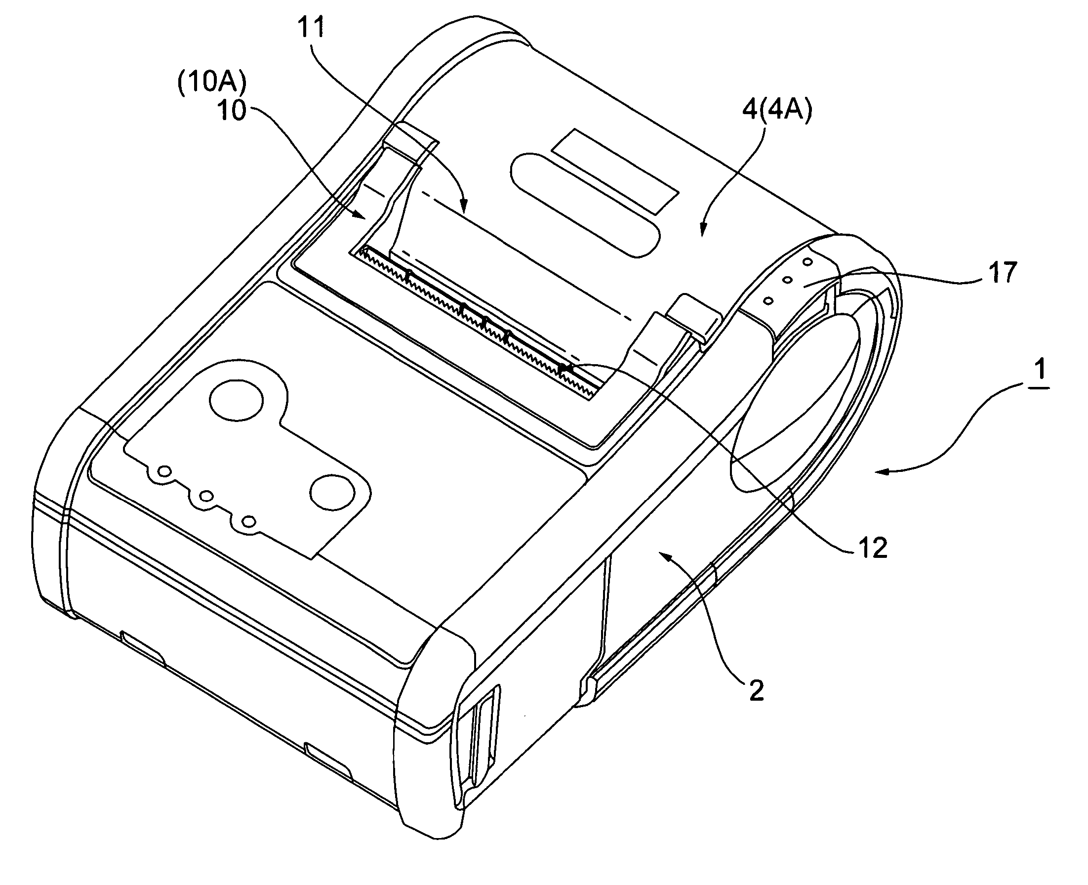
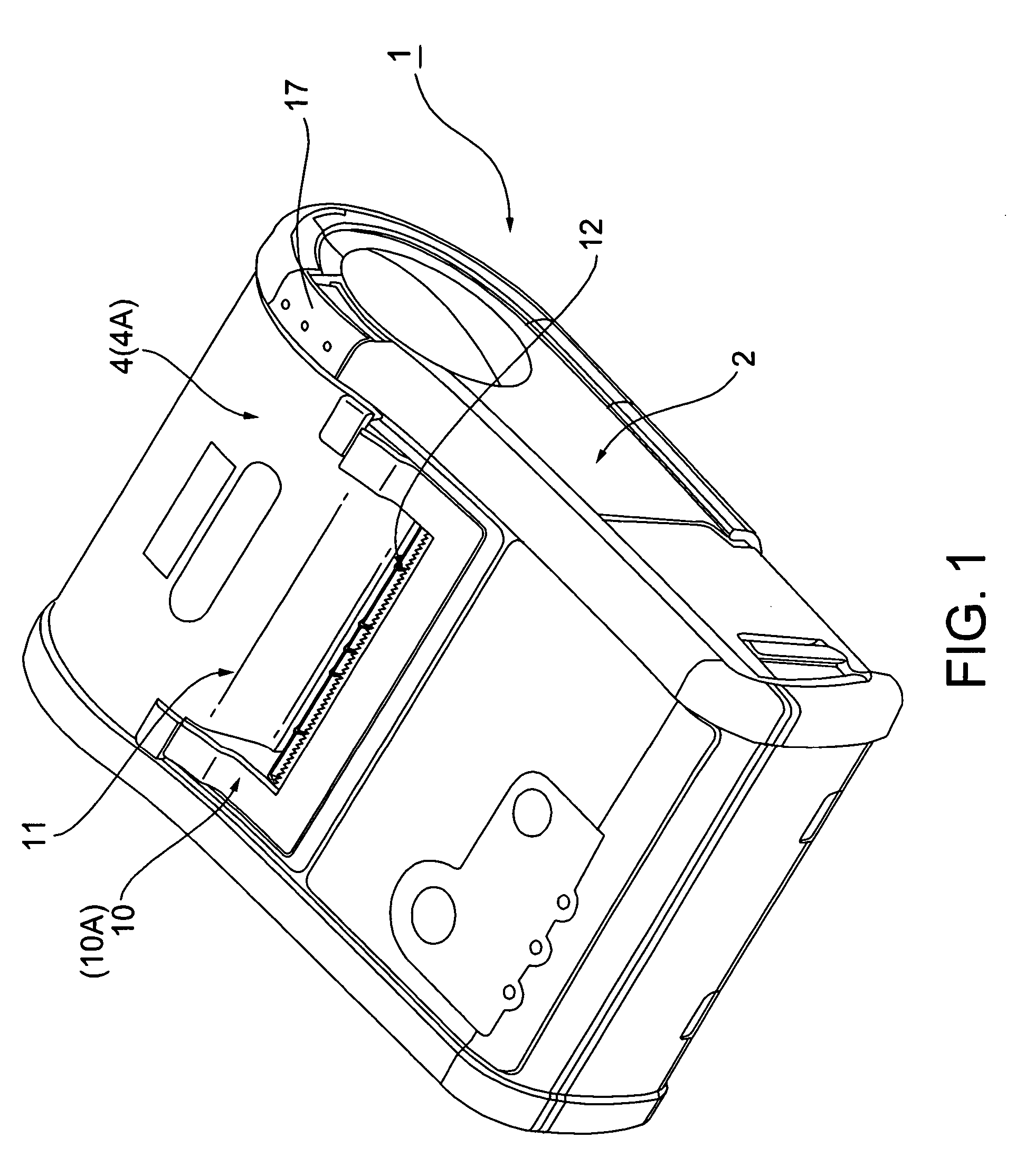
[0052] A printer with a peeler mechanism 1 according to this embodiment of the invention has a relatively flat, box-like shape as shown in FIG. 1 that is longer from front to back than across the width. An opening / closing cover 4 and an openable peeler unit 10 are disposed at the top rear portion of the printer case 2 of the printer with a peeler mechanism 1. A web exit 11 extending widthwise to the printer is formed between the opening / closing cover 4 and the peeler unit 10. A label exit 12 also extending widthwise to the printer is rendered to the peeler unit 10.

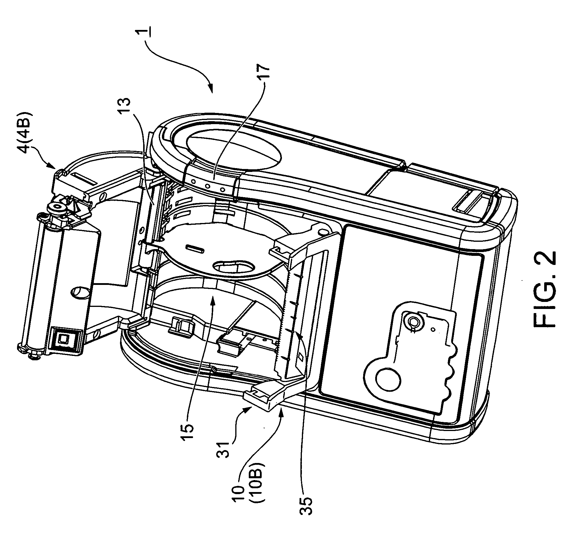
[0053] As shown in FIG. 2, the back end part of the opening / closing cover 4 is pivotally supported by a pivot shaft 13 extending widthwise to the printer on the printer body. The opening / closing cover 4 can pivot between the close...

embodiment 2

[0103] A printer with a peeler mechanism according to a second embodiment of the invention is described next with reference to FIG. 10 to FIG. 15.

[0104] General Configuration

[0105]FIG. 10 is an oblique view showing a printer with a peeler mechanism according to this embodiment of the invention, FIG. 11 is an oblique view showing the printer with the opening / closing cover open and the bottom part of the printer case removed, and FIG. 12 is a section view showing the transportation paths for the recording medium (a roll paper, a label and a web). The general arrangement of a printer with a peeler mechanism according to this embodiment of the invention is described below with reference to these figures.

[0106] The basic arrangement of a printer with a peeler mechanism 100 according to this embodiment of the invention is the same as the printer with a peeler mechanism 1 according to the first embodiment, and as shown in FIG. 10 has a relatively flat, box-like shape that is longer from...


PUM

PropertyMeasurementUnit
Currentaaaaaaaaaa
Digital informationaaaaaaaaaa
Pressureaaaaaaaaaa

Abstract

A printer with a peeler mechanism 1 for peeling labels from a web, the printer having a movable web pressure roller 24 which may be moved from a web pressure position 24A in which pressure is applied to a platen roller 20 to a retracted position 24B in which pressure is not applied. The printer also has a photosensor 21 and photoreceptor having an emitter/receptor surface 21a for detecting the presence and absence of labels peeled from the web. A window 22b in the label guide surface 22a becomes covered to shield the photosensor output for defining a no-label detection stateWhether the peeler mechanism is set to operate in the label peeling mode or is set to a retracted position defining a non-peeling continuous label dispensing mode of operation can be determined based on the output of the label detection photosensor 21, and the label dispensing mode can be set to the label peeling mode or continuous label dispensing mode based on this determination.

Description

TECHNICAL FIELD [0001] The present invention relates to a printer comprising a peeler for peeling labels from a web, and more particularly to a printer comprising a peeler having an adjustable member that can switch the peeler between an operating mode for peeling and dispensing labels one at a time, and a separate operating mode for discharging the web with (printing) labels thereon continuously without peeling off the labels. BACKGROUND ART [0002] The peeler mechanism in a printer with a label peeler guides the web on which the labels are adhesively affixed around a peeler bar or other peeler member at an angle of 90 degrees or less. When the web is thus guided through a transportation path that curves in an acute angle, the stiffness of the labels affixed to the web surface causes the labels to peel away and separate from the web. The peeled labels are then discharged from a label exit, and the operator can easily remove the peeled labels thus dispensed from the label exit. [0003...

Claims


Application Information

Patent Timeline
IPC IPC(8): B65C11/02B32B37/00
CPCB41J3/4075B41J15/04Y10T156/1702Y10T156/16Y10T156/1994
Inventor MURATA, SHOICHIKAWAKAMI, HIDEKIYAMADA, MASAHIKOKIMURA, TOMOAKI
Owner SEIKO EPSON CORP
Why Eureka
Try Eureka