Butt welding device and butt welding method

a welding device and butt welding technology, applied in the direction of welding with roller electrodes, manufacturing tools, rolling electrodes, etc., to achieve the effect of reducing butt welding work time and high efficiency

Inactive Publication Date: 2006-07-13
SUMITOMO METAL IND LTD +1
View PDF4 Cites 6 Cited by
  • Summary
  • Abstract
  • Description
  • Claims
  • Application Information

AI Technical Summary

Benefits of technology

[0029] When the pair of electrode members are constituted of the latter pair of block electrodes, a butt welding work on a plate member can be finished by once pressing a b...

Problems solved by technology

However, according to the conventional butt welding appara...

Method used


Image

  • Butt welding device and butt welding method
  • Butt welding device and butt welding method
  • Butt welding device and butt welding method

Examples


Embodiment Construction

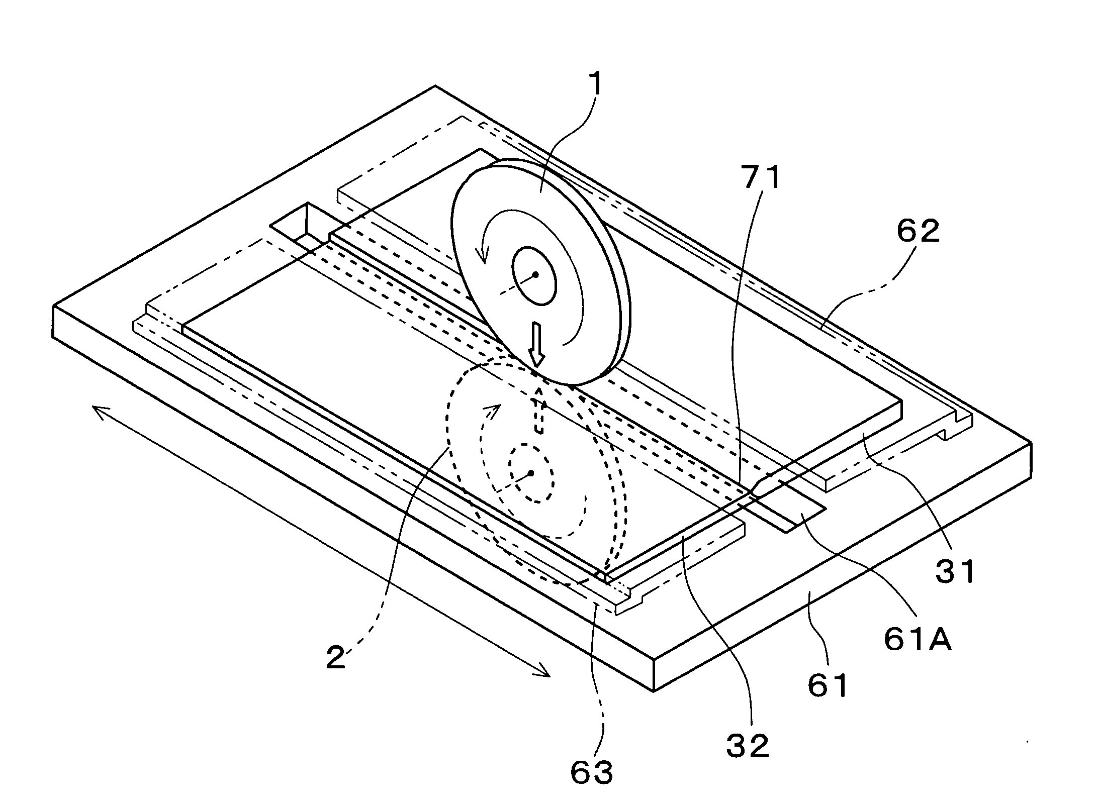
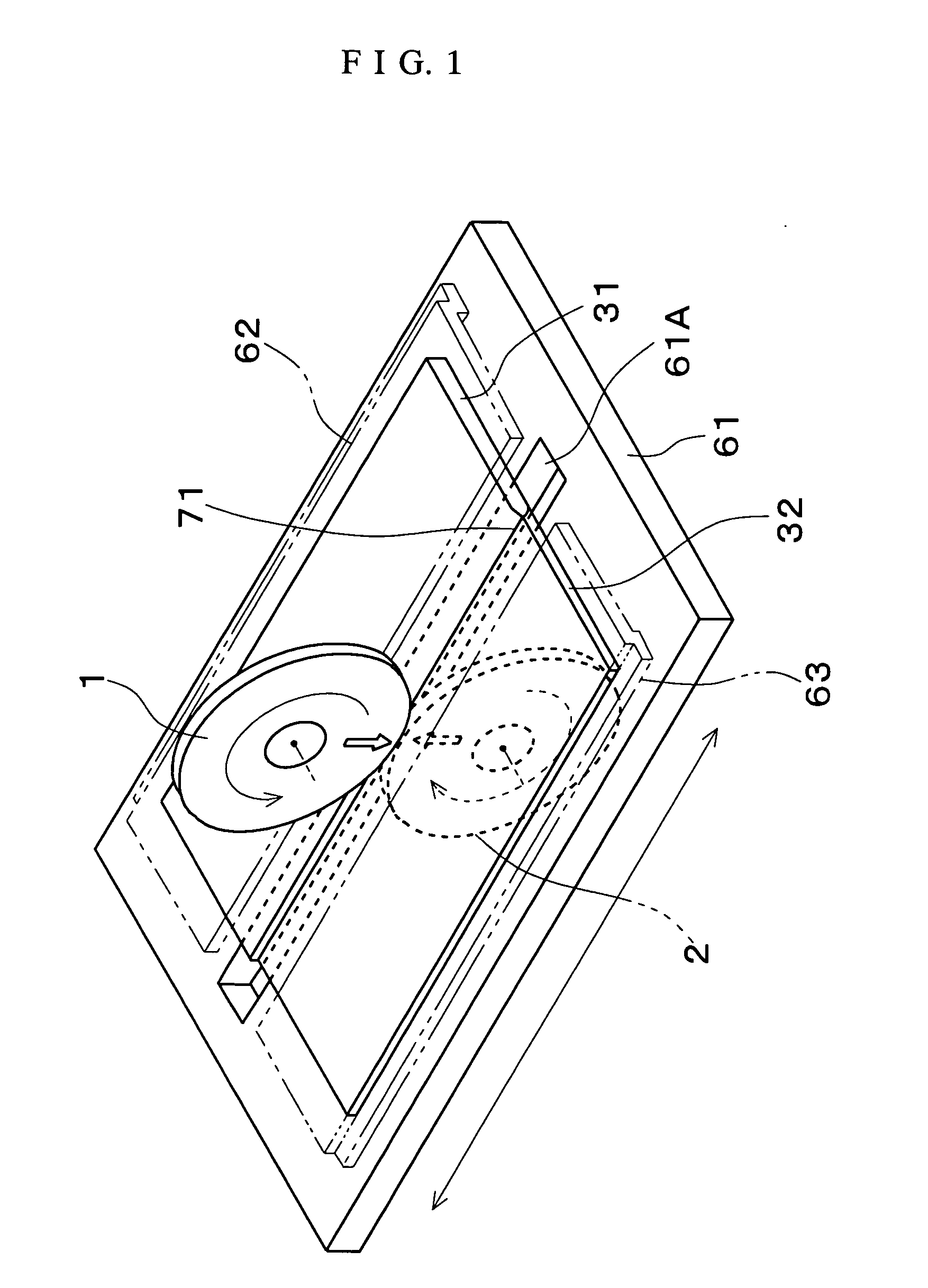
[0067] The present invention will be described in more detail with reference to the accompanying drawings. FIG. 1 is a perspective view schematically showing a butt welding apparatus according to an embodiment of the present invention. Two plate members to be welded 31, 32 each composed of a steel plate or another metal plate are butted and fixedly set to a work table 61 of a welding apparatus by fixing tools 62, 63. One of the plate members is a thick plate member 31 having a large thickness size and the other plate member is a thin plate member 32 having a small thickness size.

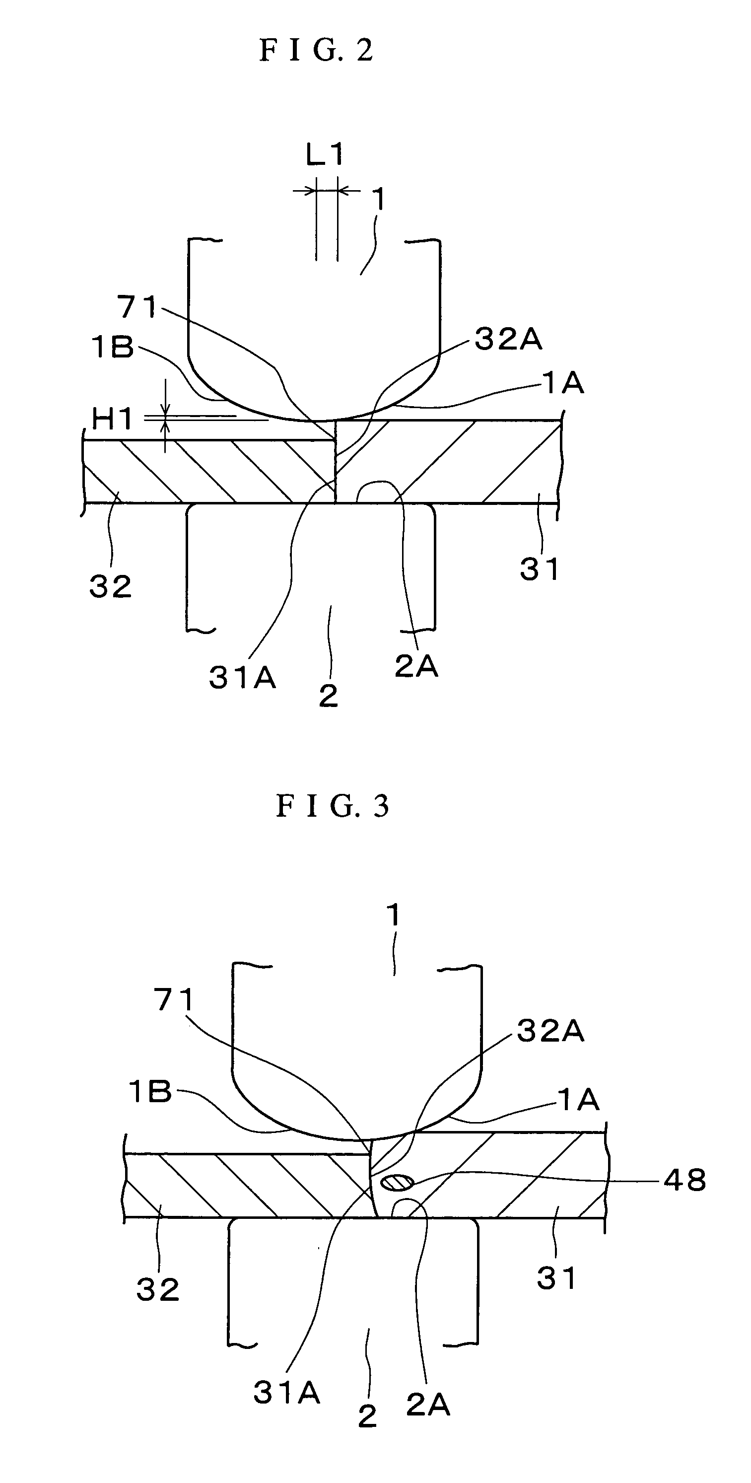
[0068]FIG. 2 shows a butt portion 71 of an end face 31A of the thick plate member 31 and an end face 32A of the thin plate member 32 in an enlarged manner. The butt portion 71 is coincident with the position of an elongated opening portion 61A of the work table 61 shown in FIG. 1, and two electrode rollers 1 and 2 serving as a pair of two electrode members for butt-welding the butt portion 71 with electric ...


PUM

PropertyMeasurementUnit
Currentaaaaaaaaaa
Thicknessaaaaaaaaaa
Electrical resistanceaaaaaaaaaa

Abstract

The present invention is a butt welding apparatus and a butt welding method where end faces of at least one plate member to be welded are butted to each other to form a butt portion, and butt welding can be performed on respective plate members to be welded which have various thickness sizes on both side portions of the butt portion with electric resistance heat by a pair of two electrode members which are made common to the respective plate members and are supplied with power. At least one electrode member (1) of a pair of electrode members (1, 2) for butt-welding two plate members (31, 32) is provided on an outer face thereof with a retreating-shaped portion (1A) which gradually retreats from one plate member (31) of the two plate members (31, 32) according to extension from an intermediate portion, in a thickness direction, of the one electrode member (1) along the one plate member (31). Butt welding of the two plate members (31, 32) is performed in a state that the position of the butting portion (71) of these plate members (31, 32) has been offset from intermediate portions, in thickness directions, of the electrode members (1, 2) to the retreating-shaped portion (1A) by an amount (L1) corresponding to a difference in thickness between the plate members (31, 32), and butt welding of two other plate members having different thickness sizes is performed with a changed offset amount.

Description

BACKGROUND OF THE INVENTION [0001] 1. Technical Field [0002] The present invention relates to a butt welding apparatus and a butt welding method for melting and joining a butt portion obtained by butting end faces of at least one plate member to be welded to each other with electric resistance heat generated by supplying power between a pair of two electrode members. [0003] 2. Background Art [0004] JP2003-305572A describes a butt welding apparatus where a pair of two electrode members are arranged at a butt portion formed by butting end faces of two plate members to be welded to each other and the butt portion is melted and joined with electric resistance heat generated by applying power between the electrode members. [0005] The conventional butt welding apparatus is a butt welding apparatus having a pair of two electrode members disposed on both sides of two plate members to be welded in a thickness direction thereof, end faces of the two plate members being butted to each other to...

Claims


Application Information

Patent Timeline
IPC IPC(8): B23K11/06B23K11/30
CPCB23K11/06B23K11/061B23K11/3036
Inventor MIYAMOTO, YUTAKAMINAGAWA, TAKAOINAGAKI, SHINICHIFUKUI, KIYOYUKI
Owner SUMITOMO METAL IND LTD
Why Eureka
Try Eureka